
Device and method for detecting flowing speed of inflow airflow of biosafety cabinet

A technology for biological safety cabinets and detection devices, which is applied in measuring devices, fluid velocity measurement, velocity/acceleration/impact measurement, etc., which can solve the problems of increasing detection personnel’s chances of contacting hazardous objects, non-reproducibility, and low positioning accuracy , to achieve the effects of saving detection time, reducing the risk of biological hazards, and reducing the risk of biological hazards

Pending Publication Date: 2020-09-25
上海豪米建设工程技术服务有限公司
View PDF0 Cites 2 Cited by
  • Summary
  • Abstract
  • Description
  • Claims
  • Application Information

AI Technical Summary

Problems solved by technology

This has just caused the following serious problems: 1) Since the inspector needs to hold the anemometer for a long time to detect at the front window operation port, the detection takes a long time, which greatly increases the chance of contact between the inspector and the hazards in the biological safety cabinet, increasing 2) The inspectors have to use a steel tape to locate the abscissa every time, and the scale that comes with the probe of the hand-held anemometer to locate the ordinate, which takes a long time and the positioning accuracy is extremely low. No reproducibility; 3) Low work efficiency: The inspectors hold the anemometer probe in one hand and the anemometer host in the other, and cannot record and detect data at the same time. Two people are required to carry out at the same time, one for testing and one for recording data

Method used


Image

  • Device and method for detecting flowing speed of inflow airflow of biosafety cabinet
  • Device and method for detecting flowing speed of inflow airflow of biosafety cabinet
  • Device and method for detecting flowing speed of inflow airflow of biosafety cabinet

Examples


Embodiment Construction

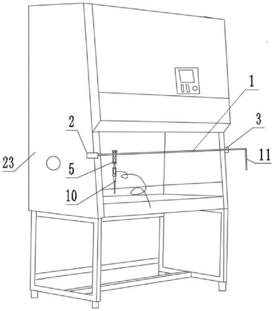
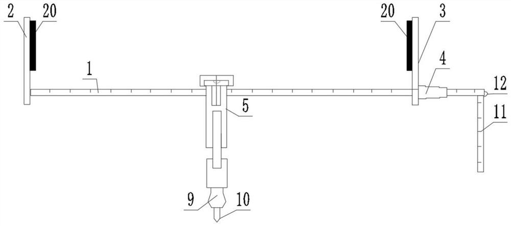
[0034] like Figure 1-9 As shown, this embodiment is used to detect the flow rate of the inflow airflow of the biological safety cabinet, which includes a support rod 1, one end of the support rod 1 is vertically fixed with a first splint 2, and the support rod 1 is pierced with a second splint 3. The second splint 3 is slidably set on the support rod 1, and the side of the second splint 3 away from the first splint 2 is fixed with a fastening device 4, and an airflow is provided between the first splint 2 and the second splint 3 The detection device 5, the air flow detection device 5 is installed on the support rod 1, and the scales are uniformly and continuously distributed on the support rod 1. An elastic cord 12 is provided, and one end of the elastic cord 12 is fixed on the first splint 2, and the other end of the elastic cord 12 is fixed on the rightmost extension bar among the plurality of extension bars 11, and the air flow detection device 5 includes a connecting plat...


PUM


Abstract

The invention discloses a device and method for detecting the flowing speed of an inflow airflow of a biosafety cabinet. The device comprises a supporting rod, and a first clamping plate is verticallyfixed at one end of the supporting rod; a second clamping plate penetrates through the supporting rod; the second clamping plate is slidably arranged on the supporting rod; a fastening device is fixedly arranged on one side of the second clamping plate; an airflow detection device is arranged between the first clamping plate and the second clamping plate; the airflow detection device is arrangedon the supporting rod in a penetrating mode and comprises a connecting plate, the upper portion of the connecting plate is in an inverted-U shape, the connecting plate is hung on the supporting rod, atransparent box is arranged on the connecting plate, horizontal bubbles are distributed in the transparent box, a clamp is fixed to the lower end of the supporting plate, and an anemograph probe is clamped at the lower end opening of the clamp. The device is simple in structure and convenient to install and use, the detection method is convenient in detection, the detection time is saved, the harm to the detection personnel is greatly reduced, and the detection result is accurate.

Description

technical field [0001] The invention belongs to the field of medical biological protection equipment, and in particular relates to a detection device and a detection method for the flow rate of the inflow airflow of a biological safety cabinet. Background technique [0002] Biological safety cabinet (BSC), also known as negative pressure filtration fume hood, is mainly used to prevent operators and the environment from being exposed to bioaerosols generated during experiments. This kind of equipment needs to detect its air flow rate and so on during the use process. At present, when the air flow into the biological safety cabinet is carried out, the inspector uses a steel tape to locate the abscissa at the front window operation port of the biological safety cabinet, and detects it with a hand-held anemometer. The scale that comes with the stick locates the ordinate, locates the approximate position of each detection point in the air, and then uses the hand-held anemometer f...

Claims


Application Information

Patent Timeline
Patent Type & Authority Applications(China)
IPC IPC(8): G01P5/00G01P1/00
CPCG01P5/00G01P1/00
Inventor 张杰李旖汪洋廖根清梅启新
Owner 上海豪米建设工程技术服务有限公司
Learn More