Foam brick conveying device for building

A technology for transporting devices and foam bricks, which is applied in the direction of transport and packaging, transport of filamentous materials, conveyors, etc. It can solve the problems of low transport efficiency, time-consuming and laborious, and achieve the effect of improving transport efficiency

Active Publication Date: 2020-09-25
江苏沂泽新型材料有限公司
View PDF8 Cites 2 Cited by
  • Summary
  • Abstract
  • Description
  • Claims
  • Application Information

AI Technical Summary

Problems solved by technology

[0005] In order to overcome the shortcomings of time-consuming and labor-intensive transportation and low transportation efficiency, the present invention needs to manually lift the foam bricks to the bracket. Foam brick delivery device for construction

Method used


Image

  • Foam brick conveying device for building
  • Foam brick conveying device for building
  • Foam brick conveying device for building

Examples


Embodiment 1

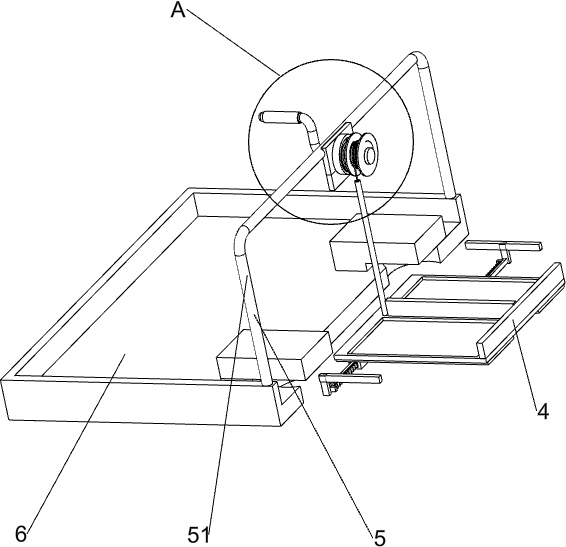
[0026] A kind of building foam brick conveying device, such as Figure 1-6 As shown, it includes a transport vehicle 1, a mounting plate 2, a transport mechanism 3, a transport plate 4, a brick shifting mechanism 5 and a support platform 6. The top of the transport vehicle 1 is vertically connected with a mounting plate 2, and a transporting plate 2 is installed on the mounting plate 2. Mechanism 3, the transport mechanism 3 is connected with a transport plate 4, the transport plate 4 is equipped with a brick moving mechanism 5, and the top of the transport vehicle 1 on the rear side of the installation plate 2 is connected with a support platform 6.

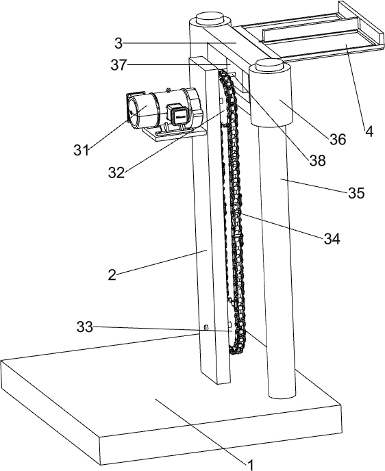
[0027] Transport mechanism 3 comprises decelerating motor 31, first sprocket wheel 32, second sprocket wheel 33, chain 34, guide rod 35, guide sleeve 36, movable block 37 and connecting rod 38, and decelerating motor 31 is installed on the back of mounting plate 2 On the upper part of the side, the output shaft of the reduction ...

Embodiment 2

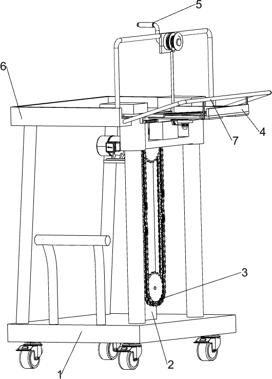
[0031] On the basis of Example 1, such as figure 1 and Figure 7 As shown, also includes lower brick mechanism 7, lower brick mechanism 7 includes fixed rod 71, second rack 72, second gear 73, cam 74, turnover plate 75 and contact plate 76, the front side upper part of support platform 6 It is connected with a fixed rod 71, and the bottom front side of the fixed rod 71 is connected with two second racks 72, and the two second racks 72 are left and right symmetrical, and the front sides of the left side and the right side of the delivery plate 4 are connected in a rotational manner. There is a second gear 73, the second gear 73 meshes with the second rack 72, the second gear 73 is connected with a cam 74, and the top rear side of the transport plate 4 is hingedly connected with two flaps 75, and the two flaps 75 are left and right. Symmetrically, the top front side of the turnover plate 75 is connected with a contact plate 76 , and the bottom of the contact plate 76 is in cont...


PUM


Abstract

The invention relates to a conveying device for building, in particular to a foam brick conveying device for building. The technical problem to be solved by the invention is how to provide the foam brick conveying device for building, which does not need to lift both hands, can save time and labor and can improve the conveying efficiency. In order to solve the technical problem, the foam brick conveying device for building comprises a conveying trolley and a supporting table, wherein the end part of the conveying trolley is connected with a mounting plate, a conveying mechanism is mounted on the mounting plate, the conveying mechanism is connected with a conveying plate, and a brick pushing mechanism is mounted on the conveying plate; and the side, closed to the end part of the mounting plate, of the conveying trolley is connected with the supporting table. Foam bricks can be rapidly conveyed to a support by moving the conveying plate upwards, so that the foam bricks do not need to beconveyed to the support manually in a high-lift mode, two hands do not need to be lifted in the high-lift mode, time and labor can be saved, and the conveying efficiency can be improved.

Description

technical field [0001] The invention relates to a construction conveying device, in particular to a construction foam brick conveying device. Background technique [0002] Due to the limited height of the wall master, when the wall master builds the wall higher, he needs to stand on a higher bracket to build the wall, so in order for the wall master to take the foam brick conveniently, the foam brick needs to be transported to the bracket At present, the foam bricks are generally lifted and transported to the support one by one by hand, which is time-consuming and laborious, and the transport efficiency is low, and it takes a long time to lift the hands high, and the hands are prone to soreness. [0003] Therefore need to research and develop a kind of building foam brick conveying device that does not need to hold hands high, can save time and effort, can improve conveying efficiency. Contents of the invention [0004] (1) Technical problems to be solved [0005] In ord...

Claims


Application Information

Patent Timeline
Patent Type & Authority Applications(China)
IPC IPC(8): B65G35/00B65H54/40
CPCB65G35/00B65H54/40
Inventor 钟翠兰
Owner 江苏沂泽新型材料有限公司
Why Eureka
Try Eureka