Placement rack for PCB production

A technology for PCB boards and racks, applied in external frames, containers to prevent mechanical damage, packaging of vulnerable items, etc., can solve the problems of PCB board production impact, PCB board surface wear, etc., to reduce the contact area and increase Friction, storage-friendly effect

Inactive Publication Date: 2020-09-25
宁夏隆基宁光仪表股份有限公司
View PDF14 Cites 0 Cited by
  • Summary
  • Abstract
  • Description
  • Claims
  • Application Information

AI Technical Summary

Problems solved by technology

A PCB board placement rack in the above-mentioned patent has the following disadvantages: when the existing placement rack stores the PCB board, the surface of the PCB board may be worn due to high friction, thereby affecting the production of the PCB board

Method used


Image

  • Placement rack for PCB production
  • Placement rack for PCB production
  • Placement rack for PCB production

Examples


Embodiment 1

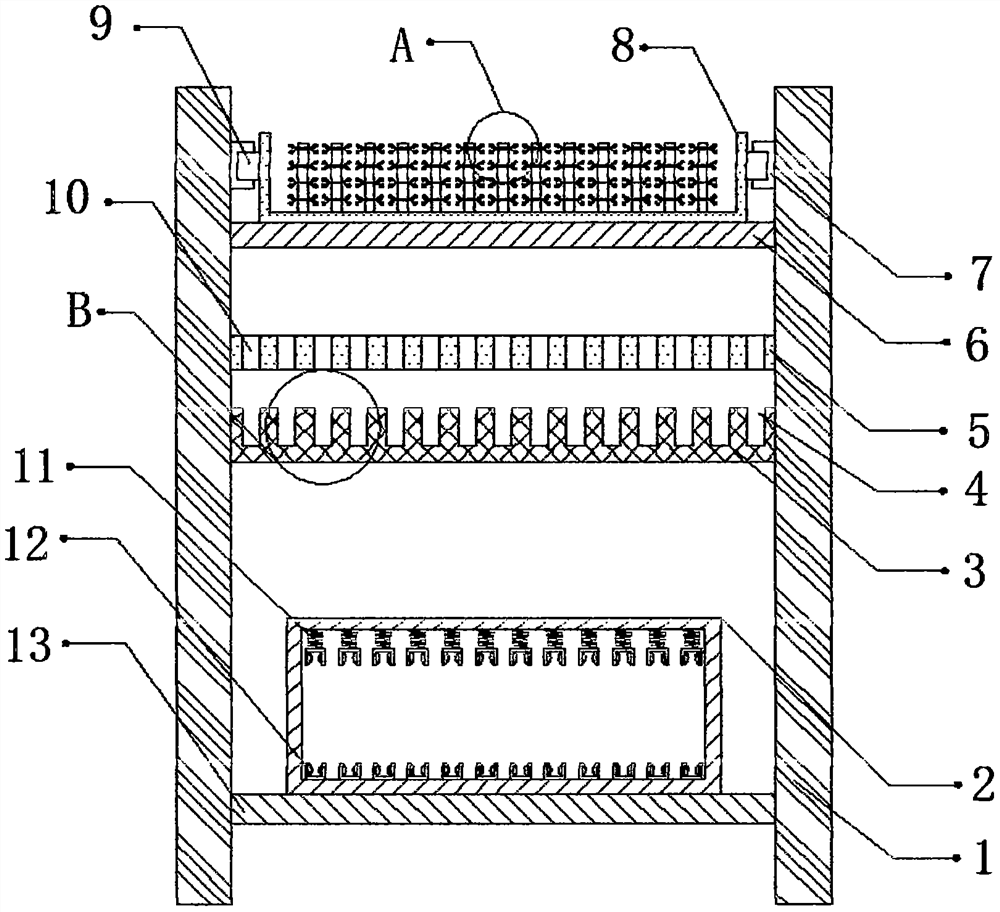
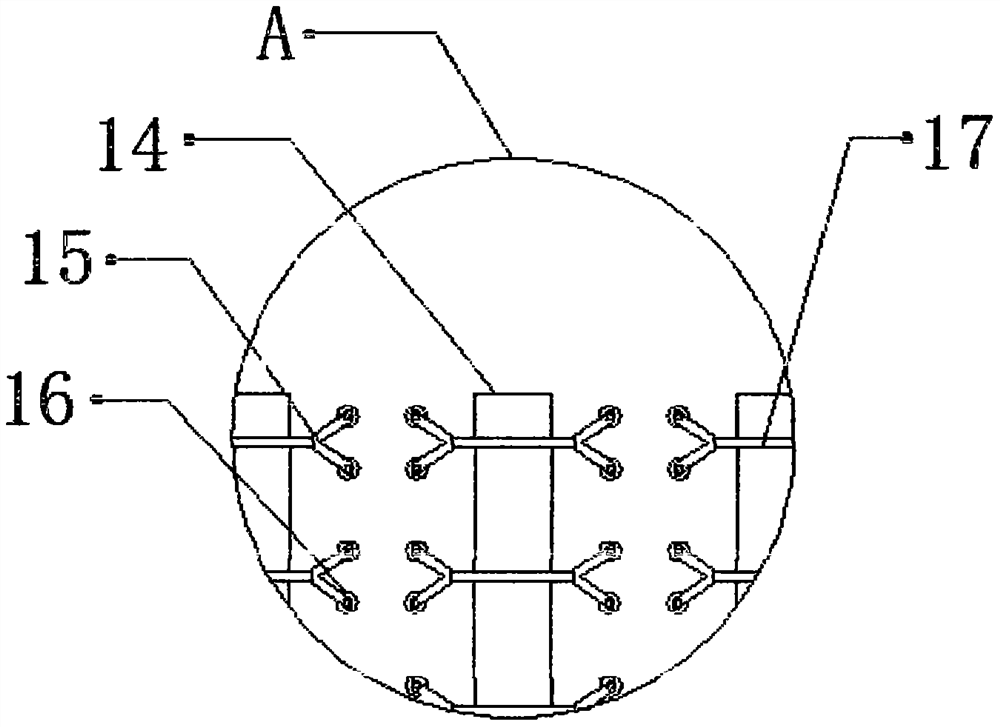
[0030] refer to Figure 1-4 , a placement rack for PCB board production, including two fixed plates 1, a fixed block 6 is connected by bolts near the top between the outer walls of the opposite side of the two fixed plates 1, and the top outer wall of the fixed block 6 is slidably connected There is a support frame 8, and the outer walls on the opposite side of the two fixed plates 1 are connected with channel steel slide rails 7 by bolts, and the inner walls on the opposite side of the two channel steel slide rails 7 are slidably connected with sliders 9. The opposite side outer walls of the block 9 are connected with the support frame 8 by bolts, and the bottom inner wall of the support frame 8 is connected with a plurality of partitions 14 by bolts, and one side outer wall of the partition 14 is provided with a plurality of through holes. The inner wall of the through hole is slidably connected with a slide bar 17, and the outer walls on both sides of the slide bar 17 are c...

Embodiment 2

[0039] refer to Figure 5 , a placement rack for PCB board production. Compared with Embodiment 1, in this embodiment, a storage plate 20 is connected by bolts between the outer walls on the opposite side of the two fixed plates 1, and the shape of the storage plate 20 is wavy. The outer wall of the top of the storage board 20 is connected with a plurality of bumps 19 by bolts, and the bumps 19 are distributed in a stepped shape. The shape of the bumps 19 is stepped, which can reduce the size of the PCB board and the storage board while storing the PCB board. The contact area between 20 is convenient for storing the PCB board.

[0040]Working principle: When in use, store the produced PCB board on the shelf, and the friction force between the clamp block 15 and the PCB board can be reduced by the ball 16, so as to facilitate the storage of the PCB board and prevent the PCB board from being damaged due to friction. The surface of the board is worn, and the shape of the clamp b...


PUM


Abstract

The invention discloses a placement rack for PCB production. The placement rack comprises two fixing boards; a fixing block is fixedly connected to the position which is close to the top and is between the outer walls of the sides, facing each other, of the two fixing boards; a supporting frame is slideably connected to the outer wall of the top of the fixing block; groove steel sliding rails arefixedly connected to the outer walls of the sides, facing each other, of the two fixing boards correspondingly; sliding blocks are slideably connected to the inner walls of the sides, facing each other, of the two groove steel sliding rails correspondingly; the outer walls of the sides, facing each other, of the two sliding blocks are connected with the supporting frame through bolts; a pluralityof partition boards are fixedly connected to the inner wall of the bottom of the supporting frame; and a plurality of through holes are formed in the outer walls of one sides of the partition boards.By means of the placement rack for PCB production, the surfaces of PCBs can be prevented from being abraded due to friction force, the PCBs can be prevented from sliding off from the inner walls of fixing grooves, thus storage of the PCBs cannot be affected, storage of the PCBs cannot be affected by too large sizes of the PCBs, and the PCBs can be conveniently stored.

Description

technical field [0001] The invention relates to the technical field of PCB board production, in particular to a placement rack for PCB board production. Background technique [0002] The important electronic component of PCB board type is the support body of electronic devices, which realizes the wiring and electrical connection or electrical insulation between various electronic components such as integrated circuits. In the process of PCB board production process, PCB boards are generally placed on PCB boards rack for storage. [0003] After searching, the Chinese patent authorization number is CN206982641U, which discloses a PCB board placement rack, including a placement rack body, a dehumidifier is installed at the bottom of one side of the placement rack body, and several load-bearing plates are horizontally placed inside the placement rack body. There are activated carbon adsorption plates installed vertically inside the main body and between two adjacent bearing pla...

Claims


Application Information

Patent Timeline
Patent Type & Authority Applications(China)
IPC IPC(8): B65D81/05B65D85/30B65D85/86B65D61/00
CPCB65D61/00B65D81/05B65D85/30
Inventor 柯生金黄波洪永生汪永江王丽
Owner 宁夏隆基宁光仪表股份有限公司
Why Eureka
Try Eureka