
Camera module and electronic equipment

A camera module and lens technology, applied in the field of cameras, can solve the problem of inability to compensate for lens shake, and achieve the effect of improving image quality

Pending Publication Date: 2020-09-22
NANCHANG O FILM OPTICAL ELECTRONICS TECH CO LTD
View PDF2 Cites 18 Cited by
  • Summary
  • Abstract
  • Description
  • Claims
  • Application Information

AI Technical Summary

Problems solved by technology

[0005] Based on this, it is necessary to provide a camera module and an electronic device for the problem that the camera shake compensation in the Roll direction cannot be performed in the prior art.

Method used


Image

  • Camera module and electronic equipment
  • Camera module and electronic equipment
  • Camera module and electronic equipment

Examples


Embodiment Construction

[0021] In order to make the above objects, features and advantages of the present invention more comprehensible, specific implementations of the present invention will be described in detail below in conjunction with the accompanying drawings. In the following description, numerous specific details are set forth in order to provide a thorough understanding of the present invention. However, the present invention can be implemented in many other ways different from those described here, and those skilled in the art can make similar improvements without departing from the connotation of the present invention, so the present invention is not limited by the specific implementations disclosed below.

[0022] It should be noted that when an element is referred to as being “fixed” to another element, it can be directly on the other element or there can also be an intervening element. When an element is referred to as being "connected to" another element, it can be directly connected ...


PUM


Abstract

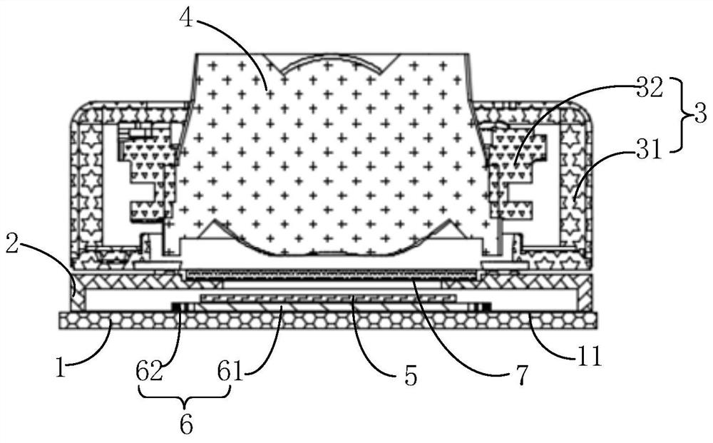
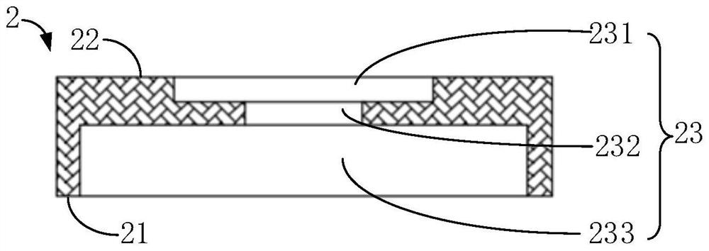
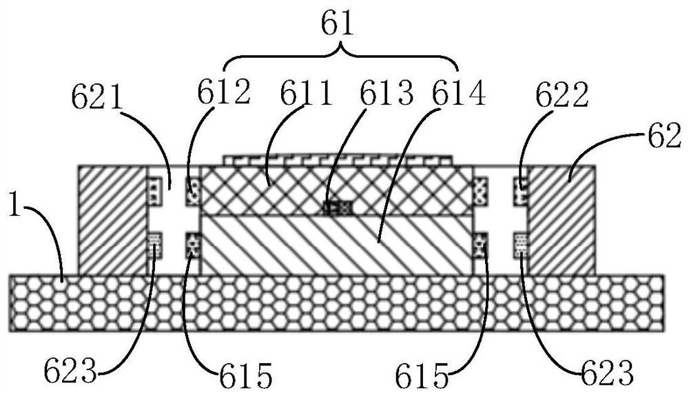
The invention relates to a camera module and electronic equipment, and the camera module comprises a substrate which is provided with an installation surface; a bracket which comprises a first surfaceand a second surface which are arranged back to back, wherein a through hole extending from the first surface to the second surface, and the mounting surface is connected with the first surface of the bracket; a voice coil motor which is arranged on the second surface of the bracket; a lens which is installed on the voice coil motor and is opposite to the through hole, wherein the voice coil motor can drive the lens to move so as to compensate image blurring caused by jitter; a photosensitive assembly which is arranged in the through hole and is opposite to the lens; and an anti-shake assembly which is arranged on the substrate and can drive the photosensitive assembly to rotate on a plane vertical to the optical axis of the lens so as to compensate image blurring caused by shake. According to the camera module, the lens can be adjusted through the voice coil motor, and the photosensitive assembly can be adjusted through the anti-shake assembly, so the shake of the lens in the Roll direction is compensated, and the imaging quality of the camera module can be greatly improved through the dual optical anti-shake mode.

Description

technical field [0001] The invention relates to the technical field of cameras, in particular to a camera module and electronic equipment. Background technique [0002] Optical Image Stabilization (OIS) currently applied to mobile phone lens modules mainly adopts lens movement technology, detects the movement of mobile phones through gyroscopes, and then uses voice coil motors, memory metals or piezoelectric materials, etc. The driving mode makes the lens move in the X-axis and Y-axis directions, and then realizes the compensation for the shake in the X-axis and Y-axis directions. For example, the camera modules disclosed in patent documents CN203377963U and TW1454733B. [0003] Wherein, the X-axis direction is perpendicular to the Y-axis direction, and the optical axis direction is the Z-axis direction, and the plane perpendicular to the optical axis is the plane where the X-axis and the Y-axis are located. The movement of the lens in the X-axis and Y-axis directions main...

Claims


Application Information

Patent Timeline
Patent Type & Authority Applications(China)
IPC IPC(8): H04M1/02H04N5/225
CPCH04M1/0264H04M1/026H04N23/57
Inventor 黄振棠陈文章林光彦
Owner NANCHANG O FILM OPTICAL ELECTRONICS TECH CO LTD
Learn More