
Fingerprint acquisition area determination method and fingerprint acquisition area determination device

A technology for fingerprint collection and area determination, which is applied in the acquisition/organization of fingerprints/palmprints, print image collection, matching and classification, etc. It can solve problems such as unfavorable fingerprint identification, lack of fingerprint information, and impact on fingerprint identification, so as to improve the user experience. Effect

Pending Publication Date: 2020-09-22
BEIJING XIAOMI MOBILE SOFTWARE CO LTD
View PDF3 Cites 0 Cited by
  • Summary
  • Abstract
  • Description
  • Claims
  • Application Information

AI Technical Summary

Problems solved by technology

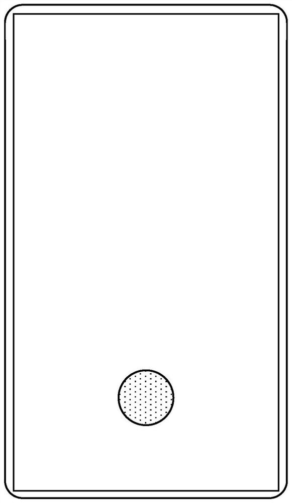
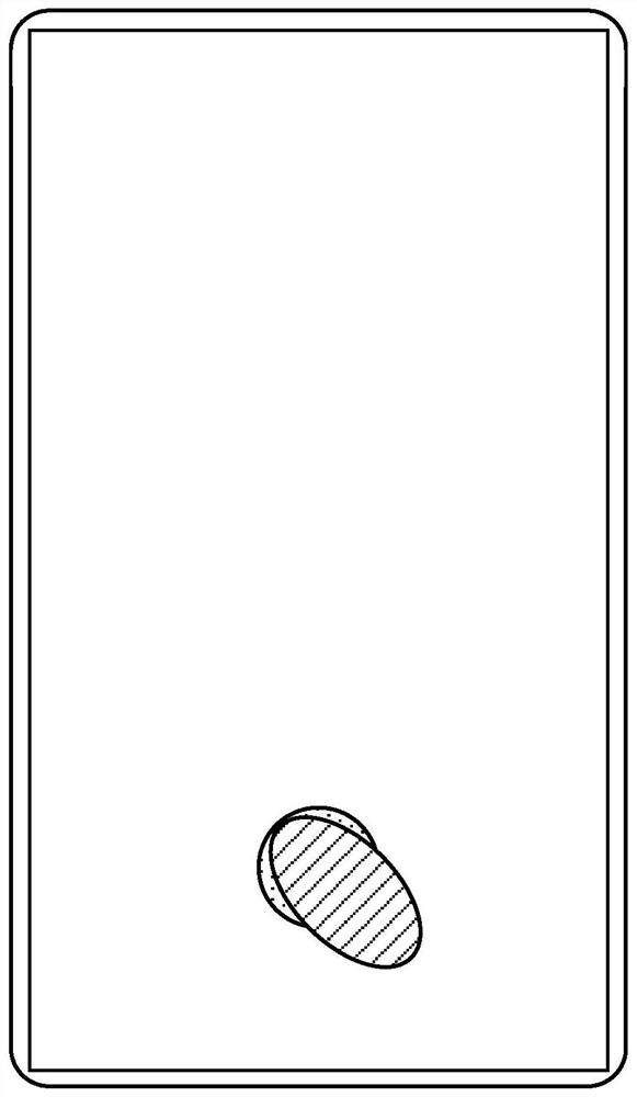
When all the fingerprint recognition sensors in the circular area are activated, for example, the fingerprint recognition sensor is a photoelectric sensor, then in figure 2 In the case shown, since the photoelectric sensor in the gap is not blocked by the finger, the leaked light will be observed by the user, which will affect the user experience, and the collected fingerprint information may not reach half of the contact area, resulting in the collection The fingerprint information is incomplete
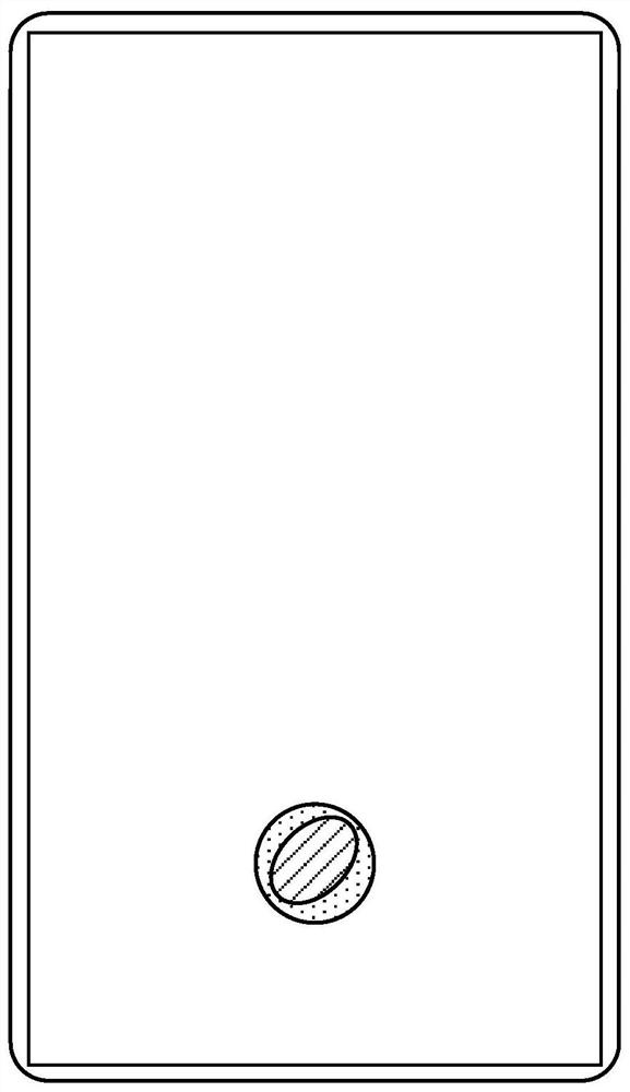
[0006] And even if the contact area is completely within the circular area, such as image 3 As shown in , since the radius of the circular area is fixed, the user can only touch part of the finger, for example, only the tip of the finger with the fingerprint collection area, which still exists figure 2 The problem of light leakage pointed out, and the collected fingerprint information is very little, which is not conducive to the identification of fingerprints
[0007] If the circular area is reduced to avoid the problem of light leakage, such as Figure 4 As shown, the circular area (area shown by the dotted line) is within the contact area due to its small area, and the collected fingerprint information is too little, which seriously affects the identification of fingerprints.

Method used


Image

  • Fingerprint acquisition area determination method and fingerprint acquisition area determination device
  • Fingerprint acquisition area determination method and fingerprint acquisition area determination device
  • Fingerprint acquisition area determination method and fingerprint acquisition area determination device

Examples


Embodiment Construction

[0089] Reference will now be made in detail to the exemplary embodiments, examples of which are illustrated in the accompanying drawings. When the following description refers to the accompanying drawings, the same numerals in different drawings refer to the same or similar elements unless otherwise indicated. The implementations described in the following exemplary examples do not represent all implementations consistent with the present disclosure. Rather, they are merely examples of apparatuses and methods consistent with aspects of the present disclosure as recited in the appended claims.

[0090] Figure 5 It is a schematic flowchart of a method for determining a fingerprint collection area according to an embodiment of the present disclosure. The fingerprint identification method shown in the embodiments of the present disclosure can be applied to terminals such as mobile phones, tablet computers, and wearable devices. The terminals include a touch module and a fingerp...


PUM


Abstract

The invention relates to a fingerprint acquisition area determination method, which comprises the steps of determining a contact area according to a touch signal generated by a touch operation from astarting moment t0 when the touch operation is sensed; determining the change rate of the characteristic characteristic parameters of the contact area; and if the change rate is smaller than or equalto a preset change rate, determining a fingerprint acquisition area according to the contact area. According to the method of the invention, the normal touch operation of the user is favorably prevented from being judged as wrong touch.

Description

technical field [0001] The present disclosure relates to the technical field of fingerprint collection, and in particular to a method for determining a fingerprint collection area, a device for determining a fingerprint collection area, electronic equipment, and a computer-readable storage medium. Background technique [0002] With the development of fingerprint identification technology, in the current terminal, fingerprint identification under the screen can be realized, that is, a fingerprint identification sensor can also be set in the display area to identify fingerprints. [0003] However, in the related art, the fingerprint identification method of setting the fingerprint identification sensor has great limitations, and the determination of the user's contact area on the terminal is only to determine the center of gravity of the contact area. The prior art summarizes the way to determine the center of gravity by weighting and averaging the touch signals. However, when...

Claims


Application Information

Patent Timeline
IPC IPC(8): G06K9/00G06F3/0488G06V10/25G06V40/13
CPCG06F3/0488G06V40/1318G06F3/04883G06F21/32G06V40/13G06V10/25G06F3/041G06F2203/04101G06V40/1365
Inventor 胡现坤唐矩
Owner BEIJING XIAOMI MOBILE SOFTWARE CO LTD
Learn More