A differential installation structure in a tractor chassis

A technology of installation structure and differential gear, which is applied in the field of tractors, can solve the problems of machining accuracy and installation accuracy error, unfavorable power transmission, large meshing gap between toothed plate and power shaft, etc., and achieve the effect of ensuring meshing stability

Active Publication Date: 2022-04-22
NINGBO KAIMING MACHINERY MFG
View PDF8 Cites 0 Cited by
  • Summary
  • Abstract
  • Description
  • Claims
  • Application Information

AI Technical Summary

Problems solved by technology

[0007] However, when the differential is installed in the chassis, due to the error of machining accuracy and installation accuracy, it is easy to cause the meshing gap between the chainring and the power shaft to be too large, which is not conducive to the transmission of power

Method used


Image

  • A differential installation structure in a tractor chassis
  • A differential installation structure in a tractor chassis
  • A differential installation structure in a tractor chassis

Examples


Embodiment Construction

[0030] The present invention will be described in further detail below in conjunction with the accompanying drawings.

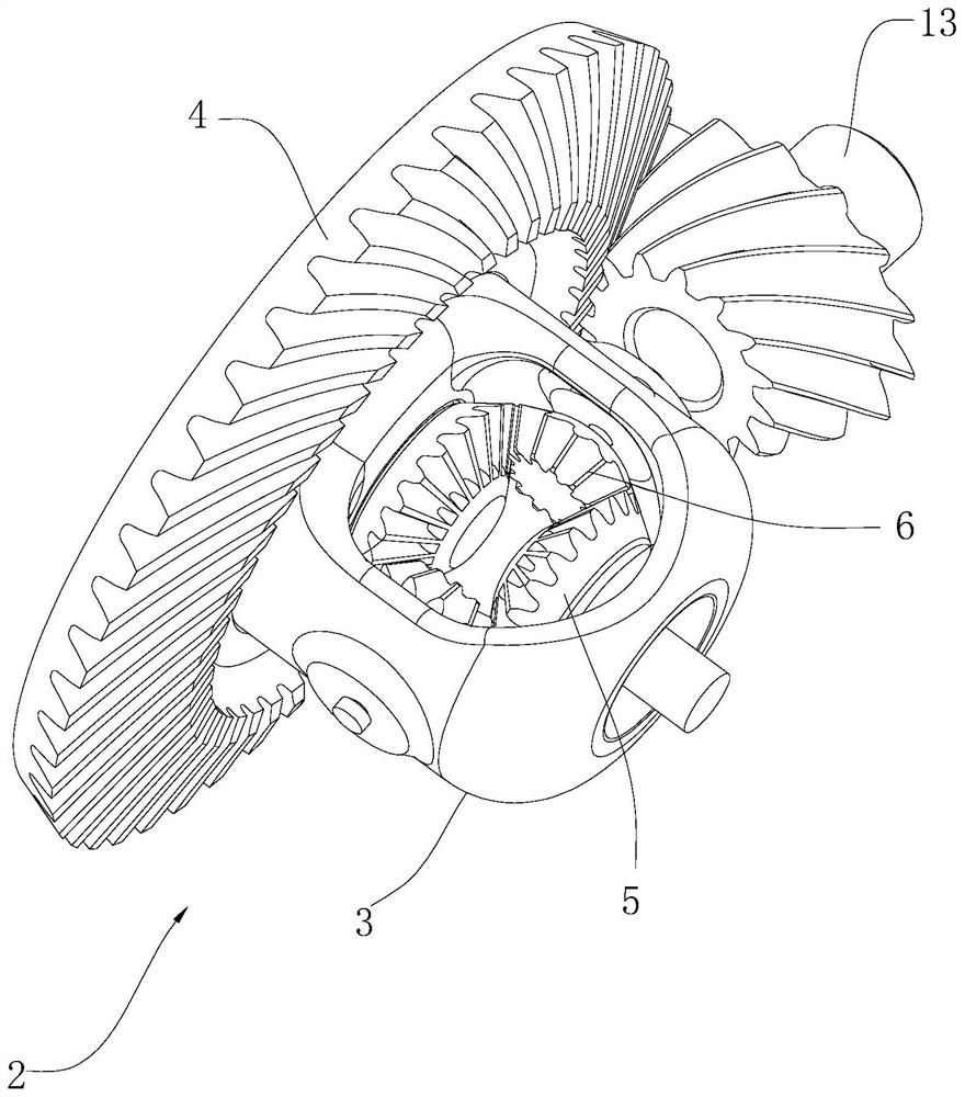
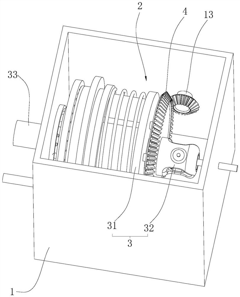
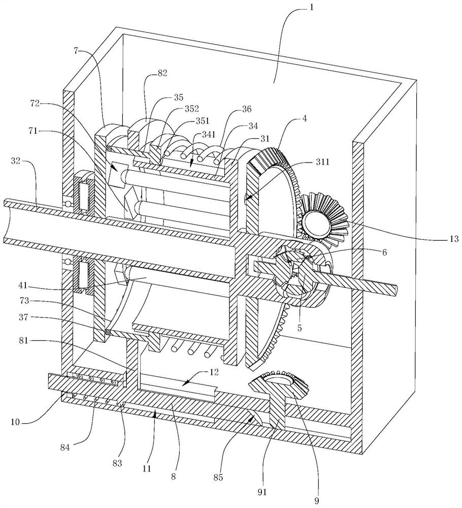
[0031] Such as figure 2 with image 3 As shown, a differential gear installation structure in a tractor chassis includes a chassis 1, a differential gear 2 and a power shaft 13 arranged in the chassis 1, and the differential gear 2 includes a housing 3 and a chainring that cooperates with the power shaft 13 4. The housing 3 includes a mounting plate 31 and a mounting portion 32. The axis of the mounting plate 31 is perpendicular to the axis of the power shaft 13. The gear plate 4 is coaxially arranged with the mounting plate 31. A pair of planetary gears are installed in the mounting portion 32 for rotation. 6 and a pair of side gears 5, the side gears 5 are coaxially arranged with the mounting plate 31, the axis of the planetary gear 6 is perpendicular to the axis of the side gears 5, and a pair of side gears 5 are respectively used for The shaft is fixed...


PUM


Abstract

The invention relates to a differential installation structure in the chassis of a tractor, which includes a chassis and a differential arranged in the chassis, the differential includes a housing and a toothed disc, the housing includes a mounting part and the same as the toothed disc The installation disk of the shaft, the upper circumferential interval of the installation disk begins to limit the limit hole, the end of the tooth disk facing the installation disk extends a limit rod through the limit hole, and the side of the installation disk away from the tooth disk is the same as The shaft extends with a fixed ring that is rotatably fixed on the chassis. An adjusting disc is arranged coaxially on the fixing ring. Adjusting bosses are arranged at intervals in the axial direction on the adjusting disc. Slidingly abutting the adjusting inclined surface, the adjusting inclined surface is set at an acute angle with the side of the adjusting plate facing the mounting plate, and an adjusting assembly for fixing the two is arranged between the fixed plate and the adjusting plate. The invention has the effect of pushing the chainring to move toward the power shaft through the adjustment disk, thereby ensuring the stability of the meshing between the chainring and the power shaft.

Description

technical field [0001] The invention relates to the technical field of tractors, in particular to a differential installation structure in the chassis of the tractor. Background technique [0002] Tractor is a self-propelled power machine used to pull and drive working machinery to complete various mobile operations. [0003] Such as figure 1 As shown, a differential 2 and a power shaft 13 are installed in the chassis of the existing tractor. The differential 2 is used to adjust the rolling speed adjustment of tires located on both sides of the tractor. The power shaft 13 provides power for the differential 2, wherein The differential 2 includes a housing 3, a toothed disc 4 is coaxially fixed outside the housing 3, and the toothed disc 4 is meshed with the power shaft 13, and a pair of side gears coaxial with the toothed disc 4 are arranged in the housing 3 5. The side gears 5 are coaxially fixedly connected to the tires on the left and right sides of the tractor, and a p...

Claims


Application Information

Patent Timeline
Patent Type & Authority Patents(China)
IPC IPC(8): F16H48/08F16H48/28F16H57/037A01B51/02
CPCF16H48/08F16H48/28F16H57/037A01B51/00F16H2057/02056
Inventor 毛培光
Owner NINGBO KAIMING MACHINERY MFG
Why Eureka
Try Eureka