Ribbon loom

A ribbon loom and load-carrying mechanism technology, applied to looms, small looms, textiles, etc., can solve the problems of lowering the quality of ribbons, the limitation of weaving silk threads, and the collision and winding of silk threads, so as to reduce processing accidents and reduce the probability of occurrence , to avoid the effect of winding

Inactive Publication Date: 2020-09-22
徐晨龙
View PDF9 Cites 1 Cited by
  • Summary
  • Abstract
  • Description
  • Claims
  • Application Information

AI Technical Summary

Problems solved by technology

[0002] Ribbon loom is a commonly used processing equipment for rope products at present. By braiding and winding various silk threads to form thicker ropes, the ropes can be elastic, and the tension resistance of the ropes can be improved, so that the ropes can be To meet the needs of different ropes in life and production, such as car seat belts, school bag straps, tag ropes, etc. With the continuous improvement of technology and the continuous improvement of use requirements, the performance of silk yarns for weaving is increasing. The number is also increasing, and usually the silk reel wrapped with silk thread is placed on the rear frame of the weaving machine, but the position of the silk reel placed on the rear frame of the current weaving machine is fixed, which limits the weaving silk thread. The space of the rack is fixed, and when there are many silk threads, it is very easy to collide and entangle the silk threads during the weaving process, which will reduce the quality of the finished webbing

Method used


Image

  • Ribbon loom
  • Ribbon loom
  • Ribbon loom

Examples


specific Embodiment approach 1

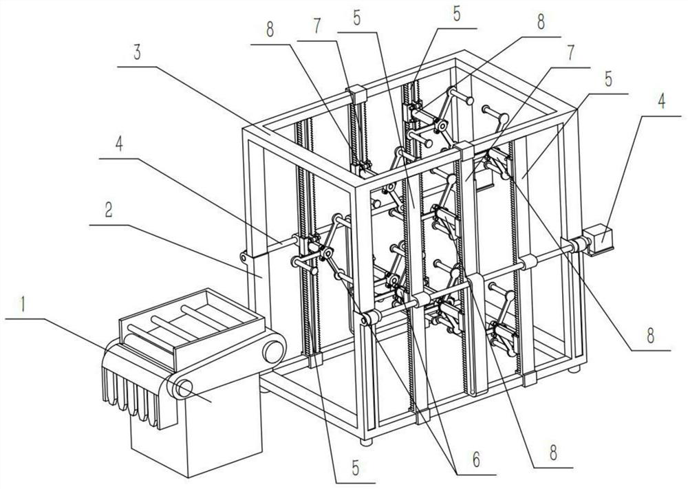
[0035] Combine below Figure 1-14 To illustrate this embodiment, a ribbon loom includes a ribbon loom 1, and the ribbon loom also includes a support base 2, a lifting frame 3, a drive mechanism 4, a column mechanism I5, a bearing mechanism I6, a column mechanism II7, and a bearing mechanism II8. The supporting base 2 is arranged on the rear side of the loom 1, the lifting frame 3 is slidably connected to the upper end of the supporting base 2, the supporting base 2 and the lifting frame 3 form a rear frame, and the driving mechanism 4 is provided with two Two driving mechanisms 4 are respectively arranged on the left and right sides of the upper end of the support base 2, and the two driving mechanisms 4 are all connected with the lifting frame 3. There are four column mechanisms I5, and the four column mechanisms I5 are two The two are relatively fixedly connected to the left and right sides of the support base 2, and two column mechanisms II7 are provided, and the two column...

specific Embodiment approach 2

[0038] Combine below Figure 1-14 This embodiment will be described. This embodiment will further describe the first embodiment. The support base 2 includes a base 2-1 and a sliding tube 2-2. There are four sliding tubes 2-2. The four sliding tubes 2- 2 are respectively fixedly connected to the four corners of the upper end of the base 2-1, the two driving mechanisms 4 are respectively arranged on the outer sides of the upper ends of the four sliding tubes 2-2, and the lower ends of the lifting frame 3 are slidably connected to the four sliding tubes. In 2-2, the four column mechanisms I5 are fixedly connected to the left and right sides of the base 2-1 in pairs.

specific Embodiment approach 3

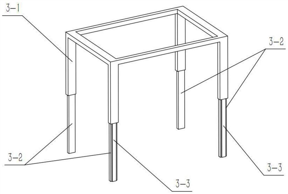
[0040] Combine below Figure 1-14 This embodiment will be described. This embodiment will further illustrate the second embodiment. The lifting frame 3 includes a bracket 3-1, a sliding rod 3-2 and a rack 3-3. The sliding rod 3-2 is provided with four One, four sliding rods 3-2 are fixedly connected to the four corners of the lower end of the bracket 3-1 respectively, and the racks 3-3 are provided with four, and the four racks 3-3 are respectively fixedly connected to the four sliding rods 3 -2 outside, the four sliding rods 3-2 are respectively slidingly connected in the four sliding tubes 2-2, and the two column mechanisms II7 are respectively fixedly connected to the left and right ends of the middle part of the bracket 3-1, and the two said The driving mechanism 4 is respectively connected with the transmission of the four racks 3-3.


PUM


Abstract

The invention relates to the technical field of ribbon weaving equipment, in particular to a ribbon loom comprising a braiding machine, a supporting base, a lifting frame, driving mechanisms, uprightpost mechanisms I, bearing mechanisms I, upright post mechanisms II and bearing mechanisms II. The supporting base is arranged at the rear side of the braiding machine; the lifting frame is connectedto the upper end of the supporting base in a sliding manner; the two driving mechanisms are respectively arranged at the left side and the right side of the upper end of the supporting base; the fourupright post mechanisms I are oppositely and fixedly connected to the left side and the right side of the supporting base in pairs; the two upright post mechanisms II are respectively fixedly connected to the middle parts of the left side and the right side of the lifting frame; the two bearing mechanisms I are respectively arranged at the inner sides of the two upright post mechanisms I at the front side; and a plurality of bearing mechanisms II are respectively arranged at the inner sides of the two upright post mechanisms I at the rear side and the inner sides of the two upright post mechanisms II. The positions of silk thread coils can be flexibly adjusted according to actual processing requirements, the space of a rear frame can be increased, the phenomenon that silk threads are woundwhen the number of the silk threads is large is avoided, and the quality of finished ribbons is improved.

Description

technical field [0001] The invention relates to the technical field of weaving equipment, in particular to a weaving machine. Background technique [0002] Ribbon loom is a commonly used processing equipment for rope products at present. By braiding and winding a variety of silk threads to form thicker ropes, the ropes can be elastic, and the tension resistance of the ropes can be improved, so that the ropes can be To meet the needs of different ropes in life and production, such as car seat belts, school bag straps, tag ropes, etc. With the continuous improvement of technology and the continuous improvement of use requirements, the performance of silk yarns for weaving is increasing. The number is also increasing. Usually, the silk reel wrapped with silk thread is placed on the rear frame of the weaving machine. The space of the rack is fixed, and when there are many silk threads, it is very easy to collide and entangle the silk threads during the weaving process, which wi...

Claims


Application Information

Patent Timeline
Patent Type & Authority Applications(China)
IPC IPC(8): D03D35/00D03D49/06
CPCD03D35/00D03D49/06
Inventor 徐晨龙
Owner 徐晨龙
Why Eureka
Try Eureka