Equipment for manufacturing knitwear raw materials by rotary centrifugal force

A technology of rotating centrifugal force and knitting, which is applied in the direction of textiles and papermaking, fiber processing, fiber cleaning machines, etc. It can solve problems such as damage, poor quality of knitted products, and affecting the quality of spinning production progress. Effect of reduction of yarn spinning transfer steps

Inactive Publication Date: 2020-09-22
海宁王骏新材料有限公司
View PDF0 Cites 1 Cited by
  • Summary
  • Abstract
  • Description
  • Claims
  • Application Information

AI Technical Summary

Problems solved by technology

[0003] Although the existing spinning assembly line can produce yarn, too many equipments are used for spinning, and the strength of the unformed yarn is relatively low during the spinning process, so it is very easy to transfer and pull the yarn between equipments. The damaged yarn will affect the production progress of the spinning and the quality of the silk thread after spinning, and finally lead to poor quality of knitted products. Therefore, a kind of equipment that uses rotating centrifugal force to make knitwear raw materials came into being.

Method used


Image

  • Equipment for manufacturing knitwear raw materials by rotary centrifugal force
  • Equipment for manufacturing knitwear raw materials by rotary centrifugal force
  • Equipment for manufacturing knitwear raw materials by rotary centrifugal force

Examples


Embodiment Construction

[0023] The following will clearly and completely describe the technical solutions in the embodiments of the present invention with reference to the accompanying drawings in the embodiments of the present invention. Obviously, the described embodiments are only some, not all, embodiments of the present invention. Based on the embodiments of the present invention, all other embodiments obtained by persons of ordinary skill in the art without making creative efforts belong to the protection scope of the present invention.

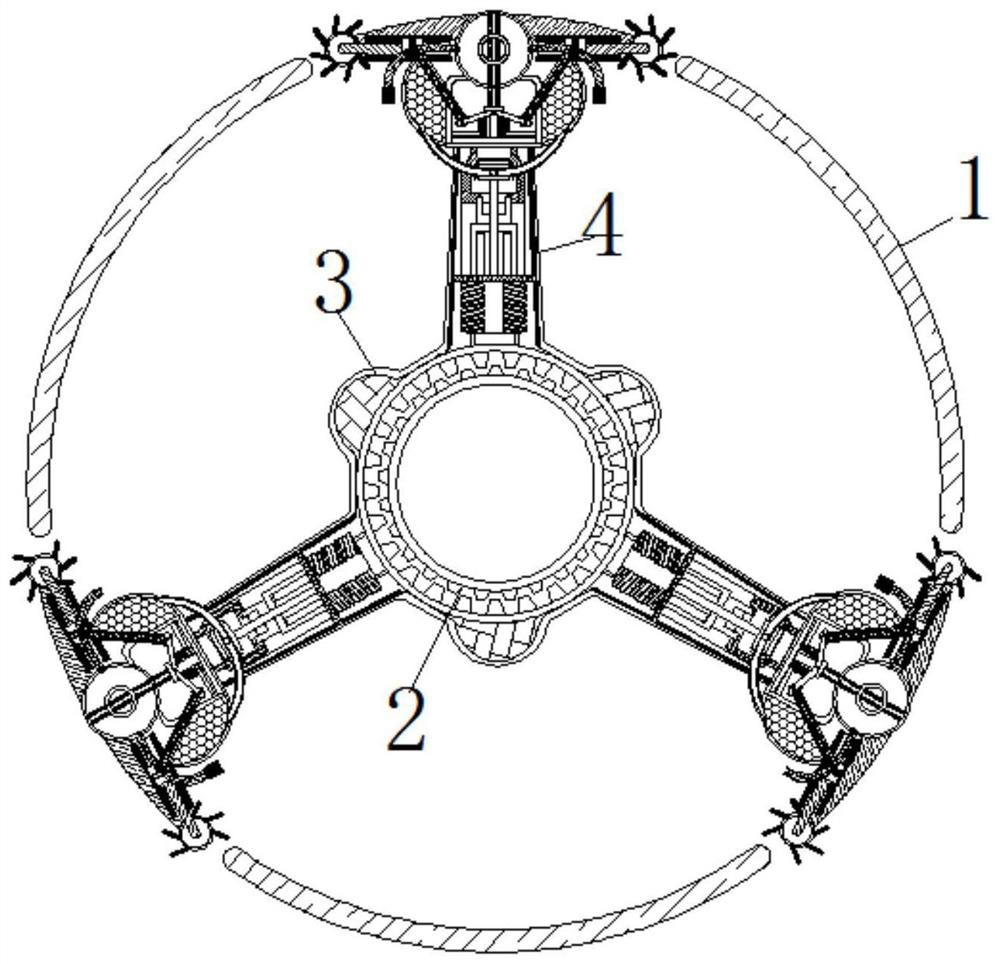
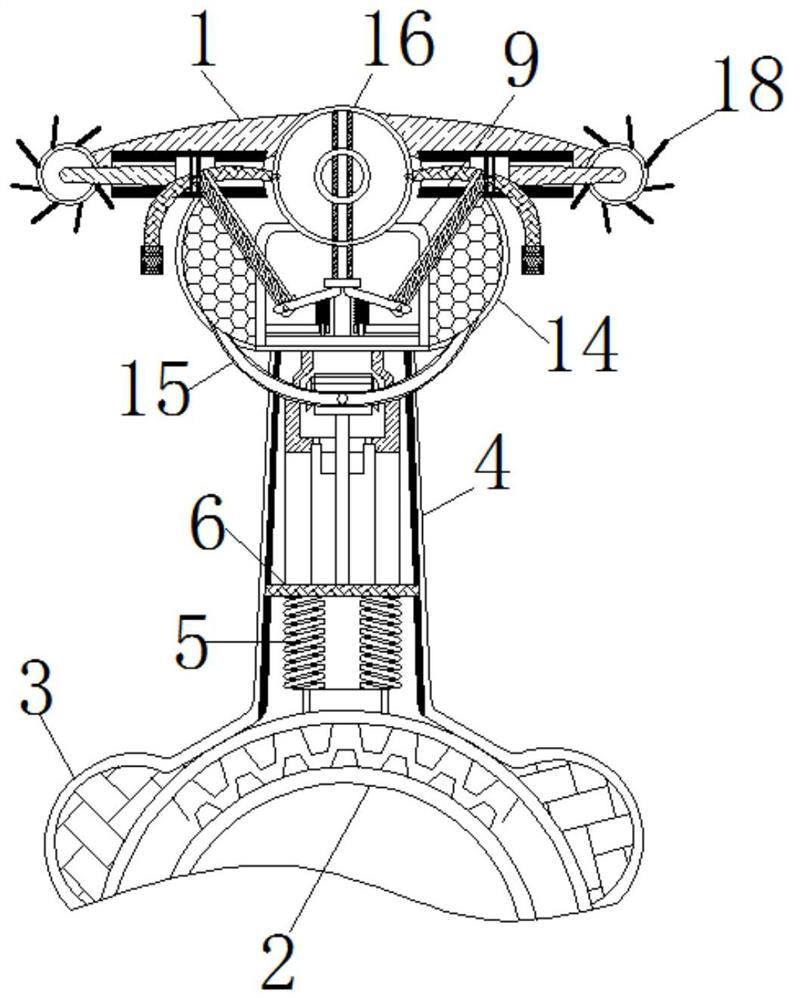
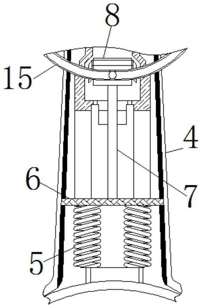
[0024] see Figure 1-6 , a kind of knitwear raw material production equipment using rotating centrifugal force, comprising a housing 1, the inside of the housing 1 is movably connected with a gear 2, the surface of the gear 2 is movably connected with an observation sleeve 3, and the surface of the observation sleeve 3 is fixedly connected with a guide plate 4 , the inside of the guide plate 4 is movably connected with a compression spring 5, and the end of th...


PUM


Abstract

The invention relates to the technical field of knitwear raw material silk yarn manufacturing, and discloses equipment for manufacturing knitwear raw materials by rotary centrifugal force. The equipment comprises a shell, a gear is movably connected into the shell, an observation sleeve is movably connected to the surface of the gear, a guiding plate is fixedly connected to the surface of the observation sleeve, a compression spring is movably connected into the guiding plate, a sliding plate is movably connected to the end, away from the guiding plate, of the compression spring, a push rod ismovably connected to the side, away from the compression spring, of the sliding plate, a piston is movably connected to the upper end of the push rod, a carding plate is fixedly connected to the end,away from the observation sleeve, of the guiding plate, a roller rod is movably connected to the end, away from a spring rod, of a lifting rod, and a knocking rod is movably connected to the joint ofthe roller rod and the lifting rod. The centrifugal force generated by rotating of the observation sleeve is gradually greater than the elastic force of the spring rod, rollers rotate to enable shortfiber to be in touch with a winding rod, and thus the effects that reducing the silk yarn spinning and transferring steps and completing spinning and cleaning are achieved.

Description

technical field [0001] The invention relates to the technical field of making knitwear raw material silk thread, in particular to a device for making knitwear raw material by using rotating centrifugal force. Background technique [0002] Knitwear is an article made by knitting technology, and the raw material of knitwear is silk thread, of which the silk thread needs to be spun, and the spinning needs to be made through steps such as impurity removal, loosening, opening, and carding. Some spinning production adopts the form of assembly line. After one process is completed, the spinning is also completed. [0003] Although the existing spinning assembly line can produce yarn, too many equipments are used for spinning, and the strength of the unformed yarn is relatively low during the spinning process, so it is very easy to transfer and pull the yarn between equipments. The damaged yarn will affect the production progress of spinning and the quality of silk thread after spin...

Claims


Application Information

Patent Timeline
Patent Type & Authority Applications(China)
IPC IPC(8): D01G9/00D01G9/14
CPCD01G9/00D01G9/14
Inventor 吴建华
Owner 海宁王骏新材料有限公司
Why Eureka
Try Eureka