Photocatalytic-thermocatalytic air purification device

An air purification device and thermal catalysis technology, applied in the field of air purification, can solve the problems of low VOCs degradation efficiency, adsorption will become a pollution source, photocatalyst deactivation, etc., and achieve the effect of easy transportation and transfer, maintaining catalytic efficiency and high catalytic efficiency

Inactive Publication Date: 2020-09-22
SOUTH CHINA UNIV OF TECH
View PDF9 Cites 0 Cited by
  • Summary
  • Abstract
  • Description
  • Claims
  • Application Information

AI Technical Summary

Problems solved by technology

The adsorption method mostly uses activated carbon. After the adsorption carbon is saturated, not only can it no longer be adsorbed, but it will also become a source of pollution. For the entire environment, it only transfers pollution and does not completely degrade it.
Ozone technology mainly has the functions of sterilization, disinfection, and deodorization. It has low degradation efficiency for VOCs, and ozone is harmful to the human body and the environment. If it is accidentally leaked, it may cause greater harm.
Although photocatalytic technology has low energy consumption, photocatalysts are cheap and non-toxic, they have high requirements for light sources, and photocatalysts are easily deactivated due to photogenerated electron-hole recombination, and are difficult to recycle.
The main disadvantage of thermal catalytic oxidation technology is the high energy consumption.

Method used


Image

  • Photocatalytic-thermocatalytic air purification device
  • Photocatalytic-thermocatalytic air purification device
  • Photocatalytic-thermocatalytic air purification device

Examples


Embodiment Construction

[0029] In order to illustrate the technical solution of the present invention more clearly, the following will specifically introduce the accompanying drawings used in the description of the prior art, and further illustrate the technical solution of the present invention in conjunction with specific embodiments.

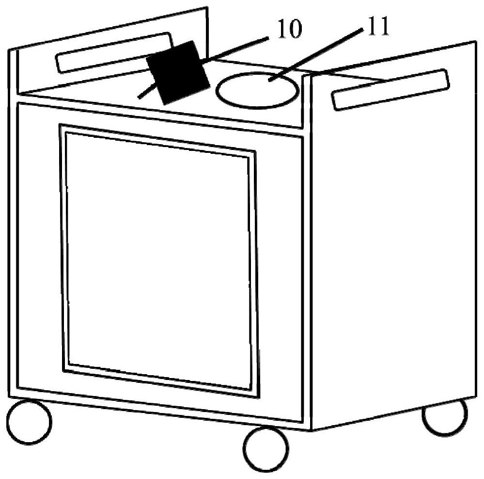
[0030] like figure 1 A photo-thermal catalysis air purification device shown, including a photoelectric conversion device, a housing, a fiber filter layer 3, a HEPA filter layer, a photo-thermal catalysis system and an activated carbon adsorption layer;

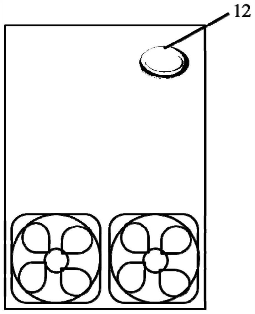
[0031] The photoelectric conversion device includes a solar cell panel 10 positioned at the top of the casing and a fan 8 placed at the exhaust port, and the solar cell panel 10 is connected to the fan 8;

[0032] The photo-thermocatalysis system includes a photothermocatalysis system and a thermocatalysis system, and the photothermocatalysis system includes a quartz light window 11 and a porous photothermocatalysi...


PUM

PropertyMeasurementUnit
thicknessaaaaaaaaaa

Abstract

The invention discloses a photocatalytic-thermocatalytic air purification device which comprises a photoelectric conversion device, a shell, a fiber filter screen layer, an HEPA filter screen layer, aphoto-thermal catalytic system and an activated carbon adsorption layer. The photoelectric conversion device comprises a solar cell panel and a fan; symmetrical handles are arranged at the upper endof the shell, gears are arranged at the lower end of the shell, an air inlet is formed in the front end of the shell, and multiple sets of clamping grooves are formed in the shell. The fiber filter screen and the HEPA filter screen are inserted into the clamping grooves close to one side of the air inlet; the surfaces of the two opposite sides of the activated carbon adsorption layer are each fixedly provided with a breathable filter membrane, the activated carbon adsorption layer is filled with honeycomb briquette activated carbon, and the activated carbon adsorption layer is inserted into the clamping groove close to an exhaust port. The photocatalytic-thermocatalytic system comprises a photo-thermal catalysis system and a thermal catalysis system. An effective solution is provided for air purification under a closed condition.

Description

technical field [0001] The invention belongs to the technical field of air purification, in particular to a photo-thermal catalytic air purification device. Background technique [0002] With the development of society, people spend more time in indoor activities, and the requirements for indoor air quality are getting higher and higher. Long-term exposure to indoor air pollutants will cause certain damage to human health, and in severe cases, it will lead to indoor air syndrome, construction-related diseases, and even cancer. VOCs and PM2.5 are the main pollutants of indoor air, mainly from household products, office supplies, printers, heat exchanger systems, insulation materials, pressed wood, wood stoves and pipe leaks, etc., the types of VOCs in various indoor environments There are more than 300 kinds. Mainly benzene series, aldehydes and halogenated hydrocarbons, more than 100 of which can directly cause harm to humans or even cause cancer, such as formaldehyde and ...

Claims


Application Information

Patent Timeline
Patent Type & Authority Applications(China)
IPC IPC(8): B01D53/86B01D53/00B01D53/04B01D53/22B01D53/44
CPCB01D46/0036B01D53/005B01D53/007B01D53/04B01D53/228B01D53/44B01D53/86B01D2255/802B01D2257/708
Inventor 丘勇才邬鹏陈光需严克友
Owner SOUTH CHINA UNIV OF TECH
Why Eureka
Try Eureka