Hydraulic oil tank, temperature control system and temperature control method

A technology of hydraulic oil tank and oil tank, which is applied in the directions of fluid pressure actuating system components, oil supply oil tank devices, fluid pressure actuating devices, etc., can solve the problems of high hydraulic oil temperature and affect the safety of hydraulic system of construction machinery, etc. safety effect

Pending Publication Date: 2020-09-18
SANY HEAVY MACHINERY
View PDF0 Cites 0 Cited by
  • Summary
  • Abstract
  • Description
  • Claims
  • Application Information

AI Technical Summary

Problems solved by technology

[0005] The purpose of the present invention is to provide a hydraulic oil tank, a temperature control system and a temperature control method to solve the technical problems that the hydraulic oil temperature is too high, which affects the use of construction machinery and the safety of the overall hydraulic system to a certain extent

Method used


Image

  • Hydraulic oil tank, temperature control system and temperature control method
  • Hydraulic oil tank, temperature control system and temperature control method

Examples


Embodiment Construction

[0026] In order to make the purpose, technical solutions and advantages of the embodiments of the present application clearer, the technical solutions in the embodiments of the present application will be clearly and completely described below in conjunction with the drawings in the embodiments of the present application. Obviously, the described embodiments are only It is a part of the embodiments of this application, not all of them. The components of the embodiments of the application generally described and illustrated in the figures herein may be arranged and designed in a variety of different configurations. Accordingly, the following detailed description of the embodiments of the application provided in the accompanying drawings is not intended to limit the scope of the claimed application, but merely represents selected embodiments of the application. Based on the embodiments of the present application, all other embodiments obtained by those skilled in the art without...


PUM


Abstract

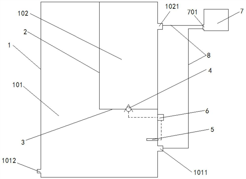
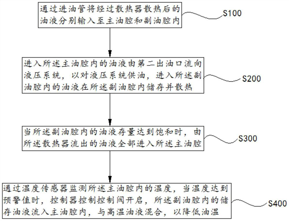
The invention provides a hydraulic oil tank, a temperature control system and a temperature control method, and relates to the technical field of hydraulic equipment. The hydraulic oil tank, the temperature control system and the temperature control method aim at solving the technical problem that the use of engineering machinery and the safety of an overall hydraulic system are influenced due toover-high temperature of hydraulic oil to a certain extent. The invention provides the hydraulic oil tank which comprises an oil tank body and a temperature control mechanism, wherein a first oil inlet and a second oil inlet are formed in the oil tank body, a partition plate is arranged in the oil tank body and divides the interior of the oil tank body into a main oil cavity and an auxiliary oil cavity, the first oil inlet communicates with the main oil cavity, the second oil inlet communicates with the auxiliary oil cavity, a first oil outlet is formed in the auxiliary oil cavity, a control valve is arranged in the first oil outlet, the control valve can block or conduct the auxiliary oil cavity and the main oil cavity, a second oil outlet is formed in the oil tank body and communicates with the main oil cavity, the temperature control mechanism is arranged in the main oil cavity and used for monitoring the oil temperature in the main oil cavity and controlling opening and closing ofthe control valve.

Description

technical field [0001] The invention relates to the technical field of hydraulic equipment, in particular to a hydraulic oil tank, a temperature control system and a temperature control method. Background technique [0002] The hydraulic oil tank is often faced with problems such as high temperature during the use of construction machinery such as excavators, resulting in excessively high hydraulic oil temperature, which affects the use of construction machinery and the safety of the entire hydraulic system. [0003] Existing ways to lower the oil temperature of the hydraulic oil usually adopt the method of adding heat dissipation structure externally to improve the heat dissipation effect. This method not only takes up space, but also increases the use cost. [0004] Therefore, it is urgent to provide a hydraulic oil tank, a temperature control system and a temperature control method to solve the problems existing in the prior art to a certain extent. Contents of the inve...

Claims


Application Information

Patent Timeline
IPC IPC(8): F15B1/26F15B21/042F15B21/0423
CPCF15B1/26F15B21/042F15B2211/62F15B21/0423
Inventor 薛庆涛陈广栋贡辉军
Owner SANY HEAVY MACHINERY
Why Eureka
Try Eureka