Window guardrail with high safety performance and capable of preventing children from falling
A safety performance and window technology, applied in the direction of windows/doors, respiratory protection containers, special equipment for doors/windows, etc., can solve the problems of reduced ventilation and lighting, low intelligence, failure to trigger protection, etc., to achieve increased startup Accurate rate, high degree of intelligence, avoiding the effect of frequent startup and accelerated aging
- Summary
- Abstract
- Description
- Claims
- Application Information
AI Technical Summary
Problems solved by technology
Method used
Image
Examples
Embodiment 1
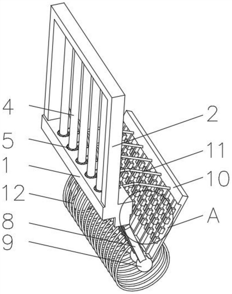
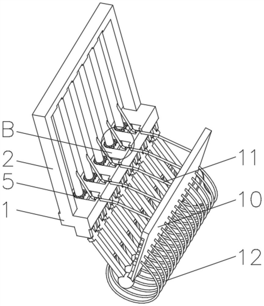
[0027] see figure 1 , 2 , 4 and 5, the present invention provides a technical solution: a window guardrail with high safety performance that can prevent children from falling, including a base 1, and a frame 2 is fixedly connected to the top of the base 1, and is characterized in that: the base 1 and the frame 2 There are chute 3 on the inner side of the chute 3, the chute 3 runs through the frame 2, railings 4 are slidably connected between the inner walls of the chute 3, the bottom of the base 1 is evenly equipped with a rotating rod 8, and the end of the rotating rod 8 away from the base 1 is passed through the card. The connecting device 9 is clamped with a baffle 10, and the outside of the railing 4 is fixedly connected with the baffle 10 through a nylon rope 11. One side of the baffle 10 is fixedly connected with a spring leaf 17, and the end of the spring leaf 17 away from the baffle 10 is connected to the rotating rod. 8 sliding connection, the base 1 is evenly provid...
Embodiment 2
[0030] see figure 1 , 2 , 4 and 5, the present invention provides a technical solution: on the basis of Embodiment 1, the bottom of the baffle plate 10 is fixedly connected with the rotating rod 8 through the load-bearing net 12, and the clamping device 9 includes a clamping ball 13, and the clamping ball The outer side of 13 is provided with a locking groove 14, the rotating rod 8 extends to the inside of the locking groove 14 and is locked and fixed with the locking groove 14, the baffle plate 10 penetrates into the inside of the locking ball 13 and is fixedly connected with the locking ball 13 . Limiting grooves 15 are provided on both sides of the inner wall of the clamping groove 14, and both sides of the rotating rod 8 are fixedly connected with protrusions 16 that are compatible with the limiting grooves 15, and the protrusions 16 extend to the inside of the limiting grooves 15 and Slidingly connected with the limit groove 15.
[0031]During use, the rotating rod 8 i...
Embodiment 3
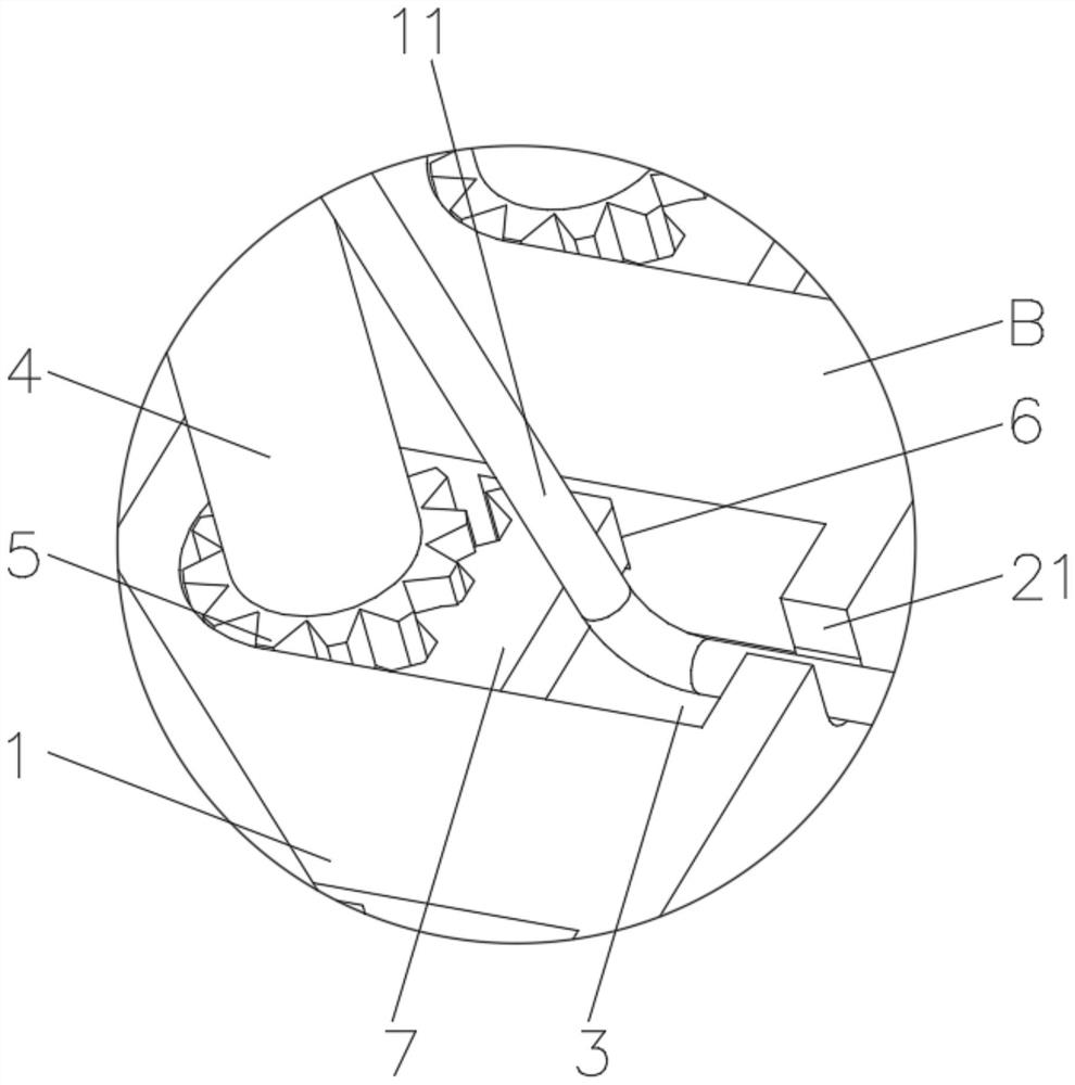
[0033] see Figure 1-5 , the present invention provides a technical solution: on the basis of Embodiment 1, gears 5 are sheathed at both ends of the railing 4, and gear plate grooves 6 are provided on both sides of the inner wall of the chute 3 close to the gear 5, A gear plate 7 is slidably connected to the bottom of the inner wall of the gear plate groove 6, and the gear plate 7 meshes with the gear 5.
[0034] When in use, when children fall from the window guardrail, they first contact the railing 4, and when they pass between the railings 4, they rub against the railing 4 to make the railing 4 rotate, and the gear 5 rotates with the railing 4, and the gear 5 drives the gear plate 7 along the gear plate groove. 6 slide until the gear plate 7 completely enters the inside of the gear plate groove 6, the railing 4 continues to be pushed to the direction of the arc groove 21 along the chute 3 after being stressed, and the nylon rope 11 is loose and no longer pulls the baffle 1...
PUM
 Abstract
Description
Claims
Application Information
 - R&D Engineer
- R&D Manager
- IP Professional
- Industry Leading Data Capabilities
- Powerful AI technology
- Patent DNA Extraction
Browse by: Latest US Patents, China's latest patents, Technical Efficacy Thesaurus, Application Domain, Technology Topic, Popular Technical Reports.
© 2024 PatSnap. All rights reserved.Legal|Privacy policy|Modern Slavery Act Transparency Statement|Sitemap|About US| Contact US: help@patsnap.com


