
An electrostatic powder spraying mechanism for building decorative steel plates and its working method

A technology for architectural decoration and spraying mechanism, which is applied in electrostatic spraying devices, liquid spraying equipment, coatings, etc. It can solve the problems of incomplete surface of powder steel plates, small range of work adaptation, and poor quality of electrostatic powder work. Achieve the effect of improving the range of work adaptation, improving the range of movement adjustment, and spraying electrostatic powder evenly

Active Publication Date: 2021-04-23
萧县华恒静电科技有限公司
View PDF6 Cites 0 Cited by
  • Summary
  • Abstract
  • Description
  • Claims
  • Application Information

AI Technical Summary

Problems solved by technology

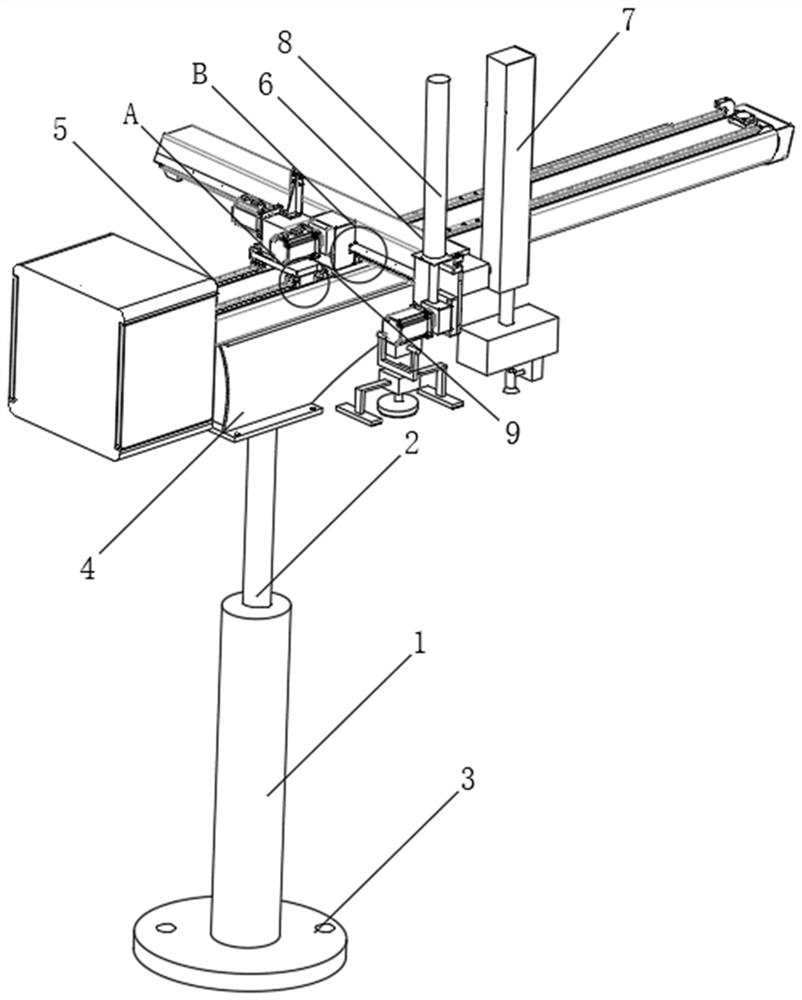
[0004] The purpose of the present invention is to solve the inaccurate working position of the existing electrostatic powder spraying mechanism for spraying electrostatic powder on the decorative steel plate, low spraying efficiency, incomplete coverage of the powder on the surface of the steel plate by spraying, and spraying of the spraying mechanism to the steel plate. The working quality of electrostatic powder is poor; the existing electrostatic powder spraying mechanism can only spray electrostatic powder on decorative steel plates of the same size and size, and the scope of work adaptation is small; after the electrostatic powder is sprayed on the surface of the steel plate, The spraying mechanism does not coat the powder evenly and smoothly on the steel plate; the existing electrostatic powder spraying mechanism has a low degree of automation and is time-consuming and labor-intensive to use, so an electrostatic powder spraying mechanism for building decorative steel plates is proposed and how it works

Method used


Image

  • An electrostatic powder spraying mechanism for building decorative steel plates and its working method
  • An electrostatic powder spraying mechanism for building decorative steel plates and its working method
  • An electrostatic powder spraying mechanism for building decorative steel plates and its working method

Examples


Embodiment Construction

[0040] The technical solutions of the present invention will be clearly and completely described below with reference to the embodiments. Obviously, the described embodiments are only a part of the embodiments of the present invention, rather than all the embodiments. Based on the embodiments of the present invention, all other embodiments obtained by those of ordinary skill in the art without creative efforts shall fall within the protection scope of the present invention.

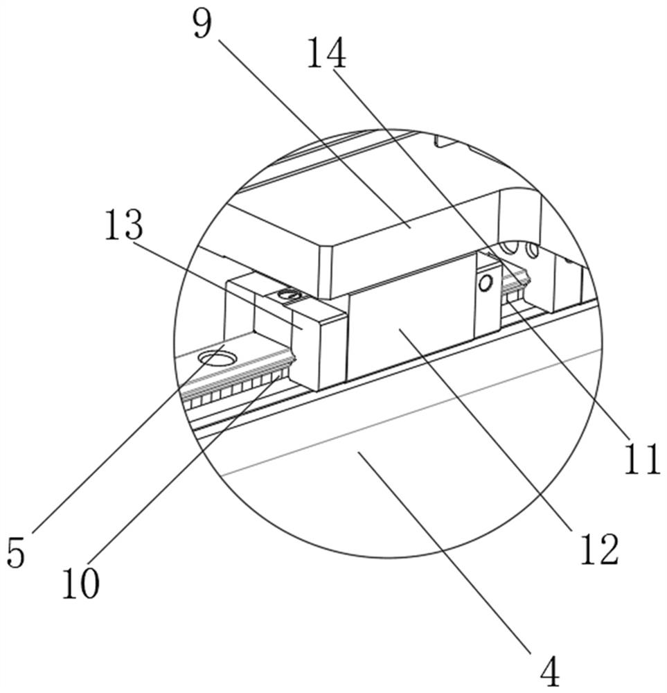
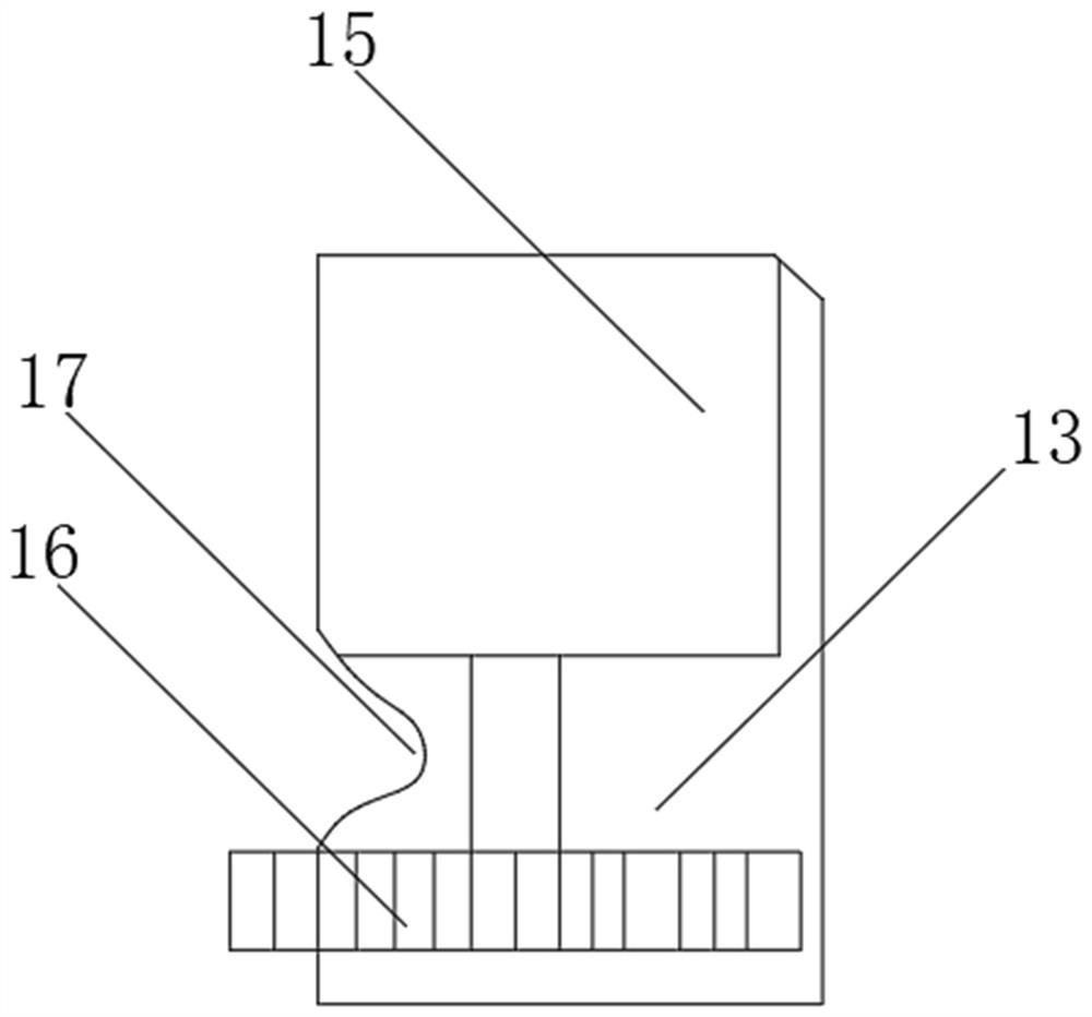
[0041] see Figure 1-9 As shown, an electrostatic powder spraying mechanism for architectural decorative steel plates includes a vertically arranged first hydraulic cylinder 1, a supporting platform 4, a material spraying assembly 7 and a spin coating assembly 8, above the first hydraulic cylinder 1 A supporting platform 4 is movably connected through the first hydraulic column 2 , first rolling rails 5 are arranged on both sides above the supporting platform 4 , and flat support plates 9 are horizontally...


PUM


Abstract

The invention discloses an electrostatic powder spraying mechanism for building decorative steel plates and a working method thereof, comprising a vertically arranged first hydraulic cylinder, a supporting platform, a material spraying assembly and a spin coating assembly. The supporting platform is movably connected through the first hydraulic column. The beneficial effect of the present invention is that: the third motor drives the second hydraulic cylinder to rotate through the first output shaft, drives the nozzle to turn over and adjust, and then cooperates with the fourth motor to drive the nozzle to rotate and adjust through the second output shaft, so as to change the nozzle's ability to spray powder on the steel plate On the one hand, it greatly improves the accuracy of the spraying mechanism for spraying electrostatic powder on the steel plate; The quality of the electrostatic powder sprayed on the steel plate; the seventh motor drives the plastic cushion to rotate through the transmission shaft to smear the molten powder, ensuring that the electrostatic powder is coated on the steel plate to cover more evenly and comprehensively.

Description

technical field [0001] The invention relates to a spraying mechanism, in particular to an electrostatic powder spraying mechanism for architectural decorative steel plates and a working method thereof, belonging to the application technical field of the electrostatic powder spraying mechanism. Background technique [0002] Architectural decorative steel plates are used more and more in house construction and home decoration. During the processing of architectural decorative steel plates, electrostatic powder spraying mechanism is required to spray electrostatic powder on the surface of decorative steel plates. The electrostatic powder forms a surface on the surface of the steel plate. The layer of "diaphragm" not only ensures that the human body will not be subjected to electrostatic shock when touching the decorative steel plate, but also acts as an insulation and anti-rust effect on the steel plate. [0003] The existing electrostatic powder spraying mechanism for building...

Claims


Application Information

Patent Timeline
Patent Type & Authority Patents(China)
IPC IPC(8): B05B5/08B05B15/00B05B15/68B05B16/20B05D3/02
CPCB05B5/081B05B5/082B05B15/00B05D3/0254B05B15/68B05B16/20
Inventor 马翠娟
Owner 萧县华恒静电科技有限公司
Learn More