Method for detecting residual stress of fiber-texture film
A technology of residual stress and detection method, which is applied in the direction of measuring force, measuring device, instrument, etc., can solve the problem of inaccurate residual stress test of silk textured film, and achieve the effect of solving inaccuracy
- Summary
- Abstract
- Description
- Claims
- Application Information
AI Technical Summary
Problems solved by technology
Method used
Image

Examples
specific Embodiment approach 1
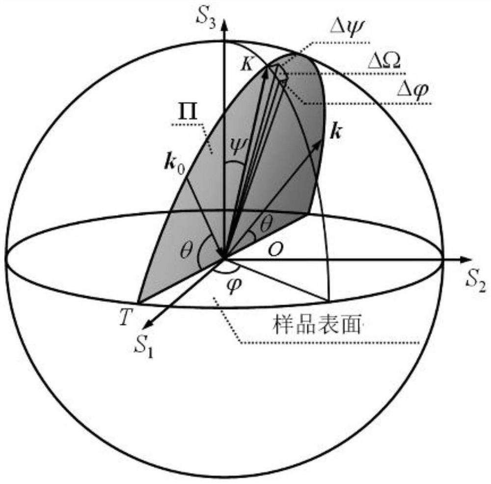
[0018] Specific implementation mode 1. Combination figure 1 , Figure 2a and Figure 2b This embodiment will be described. A method for detecting residual stress of a silk-textured thin film described in this embodiment, the method specifically includes the following steps:
[0019] Step 1. Establish a sample coordinate system S, a crystal physical coordinate system C and a test coordinate system L. The sample coordinate system S, the crystal physical coordinate system C and the test coordinate system L are all three-dimensional Cartesian coordinate systems, and the sample coordinate system S, the crystal physical coordinate system C and the test coordinate system L are concentric;
[0020] The three coordinate axes of the sample coordinate system S, the crystal physical coordinate system C and the test coordinate system L all satisfy the right-hand rule;
[0021] Step 2, transforming the flexibility tensor of the sample in the crystal physical coordinate system C to the s...
specific Embodiment approach 2
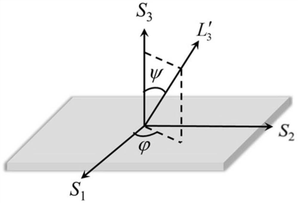
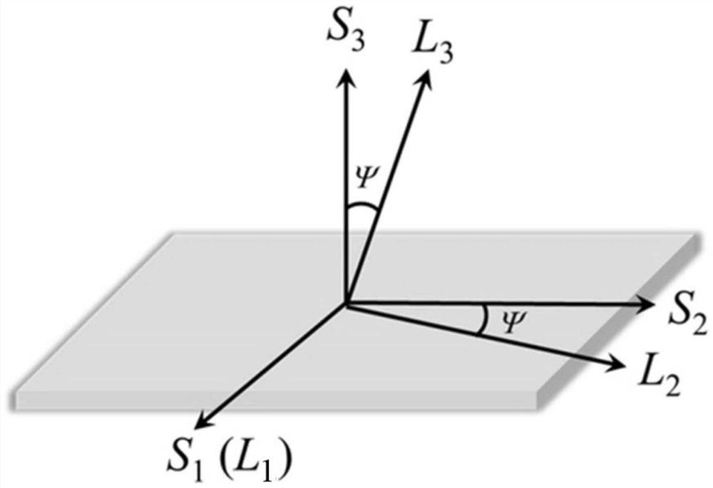
[0027] Specific embodiment two: the difference between this embodiment and specific embodiment one is that the S of the sample coordinate system S 3 The axis is perpendicular to the plane where the film surface lies, S 1 Axis and S 2 The axis is located in the plane of the film surface; the crystal physical coordinate system C is determined by the crystal structure and is completely fixed; the sample coordinate system S revolves around its own S 1 The axis is rotated by ψ angle to obtain the test coordinate system L, and the L of the test coordinate system L 3 The axis is parallel to the diffraction vector direction of the diffraction crystal plane;
[0028] Introduce the intermediate coordinate system L', taking the cubic crystal system as an example, the L' of the intermediate coordinate system L' 3 The axis is parallel to the (h, k, l,) vector in the crystal physical coordinate system C, L′ 1 axis and L' 2 The axes are respectively related to (l 2 +k 2 ,–kh,–lh) and ...
specific Embodiment approach 3
[0030] Specific embodiment 3: The difference between this embodiment and specific embodiment 2 is that in the first step, the transformation matrix a of the conversion from the sample coordinate system S to the intermediate coordinate system L' L′S for:
[0031]
[0032] Transformation matrix a for transforming crystal physical coordinate system C to intermediate coordinate system L' L′C for:
[0033]
[0034] Transformation matrix a for transforming crystal physical coordinate system C to sample coordinate system S SC for:
[0035]
[0036] Among them, (a L′S ) -1 for a L′S the inverse matrix of l 1 , l2 , l 3 、m 1 、m 2 、m 3 , n 1 , n 2 , n 3 Both are a SC Tensor elements in .
[0037] A superscript C, S, L' or L in a tensor or tensor element refers to the corresponding coordinate system in which the tensor or tensor element is located, respectively.
PUM
 Abstract
Description
Claims
Application Information
 - R&D
- Intellectual Property
- Life Sciences
- Materials
- Tech Scout
- Unparalleled Data Quality
- Higher Quality Content
- 60% Fewer Hallucinations
Browse by: Latest US Patents, China's latest patents, Technical Efficacy Thesaurus, Application Domain, Technology Topic, Popular Technical Reports.
© 2025 PatSnap. All rights reserved.Legal|Privacy policy|Modern Slavery Act Transparency Statement|Sitemap|About US| Contact US: help@patsnap.com