Butterfly valve seat purging structure

A butterfly valve and valve seat technology, which is applied in the field of butterfly valve seat purging structure, can solve the problems of easy accumulation, hardening, and ineffective purging

Pending Publication Date: 2020-09-15
JIANGSU SHENTONG VALVE
View PDF0 Cites 0 Cited by
  • Summary
  • Abstract
  • Description
  • Claims
  • Application Information

AI Technical Summary

Problems solved by technology

However, since the purge port is only on one side of the valve seat, during the compressed air purging process, only the powder medium on the valve seat side of the port can be purged, and the powder medium on other positions of the valve seat cannot be effectively purged, and accumulation is easy to occur , compaction phenomenon

Method used


Image

  • Butterfly valve seat purging structure
  • Butterfly valve seat purging structure

Examples


Embodiment Construction

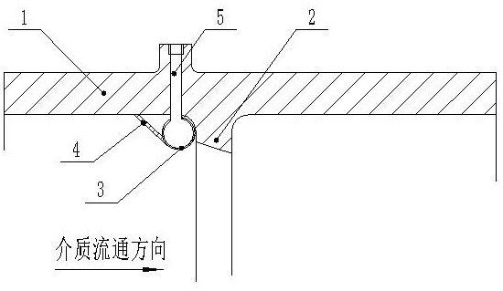
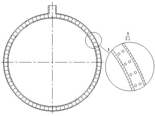
[0009] As shown in the figure, a butterfly valve seat purge structure includes a valve seat 2 and a valve body 1. The valve seat 2 is provided with a purge pipeline 3 with an air inlet 5. The purge pipeline 3 is close to the valve seat. There are through holes on the side, and the through holes are all set below the flow direction of the medium, so that the dust medium will not enter the purge pipeline 3 and block the purge pipeline 3. A baffle is provided between the valve body and the purge pipeline to ensure When the dust medium is in circulation, it will not accumulate in places where the purge pipeline 3 cannot be purged.

[0010] When purging is required, the compressed air is connected through the air inlet 5, the compressed air is introduced into the purge pipeline 3, and the valve seat is continuously purged through the through hole on the purge pipeline 3.

[0011] This specific embodiment is only an explanation of the present invention, and it is not a limitation of...


PUM


Abstract

The invention discloses a butterfly valve seat purging structure which comprises a valve seat and a valve body; a purging pipeline with an air inlet is arranged on the valve seat; through holes are formed in the side, close to the valve seat, of the purging pipeline and are formed below the medium circulating direction; and a baffle plate is arranged between the valve body and the purging pipeline. The butterfly valve seat purging structure has the following benefits: all parts of the valve seat are purged through air holes of the purging pipeline, so that the purging effects of all parts of the valve seat are ensured to be consistent, and the situation that the purging effect of certain part is not ideal to cause that the dust media are accumulated on the valve seat to affect the sealingeffect of the valve seat is prevented.

Description

technical field [0001] The invention relates to a blowing structure of a butterfly valve seat. Background technique [0002] In systems with pulverized coal and other powder media, there are hidden dangers such as powder accumulation, affecting the sealing effect of the valve, and damaging the sealing surface, especially for butterfly valves with valve seats. Since the butterfly valve contains a valve seat and the medium circulation channel contains steps, powdery medium such as coal powder is more likely to accumulate and harden, and the medium accumulates on the valve seat seal, causing the sealing surface to be worn by the medium when the valve is switched on and off, causing the valve seal to fail. In order to solve this problem, this type of valve needs an anti-accumulation structure of the valve seat, mainly a purge structure, but most of the purge structures are not ideal. [0003] In the existing technical scheme, the purge port is mainly used at the valve seat to p...

Claims


Application Information

Patent Timeline
Patent Type & Authority Applications(China)
IPC IPC(8): F16K1/32F16K1/42B08B9/032
CPCB08B9/0328F16K1/32F16K1/42
Inventor 施水杰施佳锋浦承皓胡海超石海东
Owner JIANGSU SHENTONG VALVE
Why Eureka
Try Eureka