
Submersible pump capable of stably ascending and descending

A technology for stabilizing lifting and submersible pumps, applied to pumps, parts of pumping devices for elastic fluids, pumping devices, etc., can solve problems such as unsmooth, collision damage to the inner wall of deep wells, etc., to achieve difficult movement and stable lifting Effect

Active Publication Date: 2020-09-15
TAIZHOU SRUITE IMP &EXP CO LTD
View PDF8 Cites 0 Cited by
  • Summary
  • Abstract
  • Description
  • Claims
  • Application Information

AI Technical Summary

Problems solved by technology

[0004] The purpose of the present invention is to solve the technical problem that the existing submersible pump is easy to collide with the inner wall of the deep well and be damaged during the lifting process of entering and leaving the deep well, and the entry and exit are not smooth, and to provide a stable lifting submersible pump

Method used


Image

  • Submersible pump capable of stably ascending and descending
  • Submersible pump capable of stably ascending and descending

Examples


Embodiment Construction

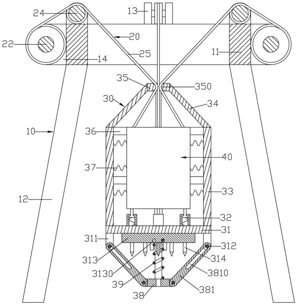
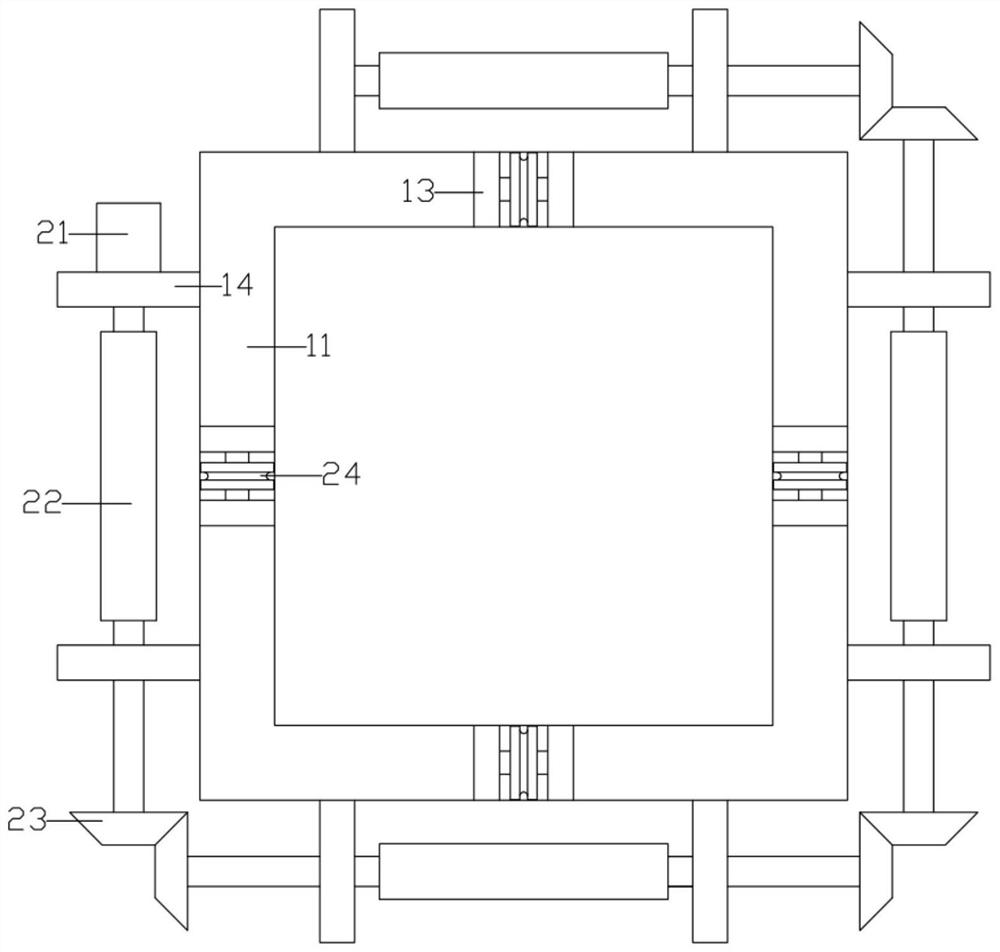
[0018] Such as figure 1 , figure 2 As shown, a stable lifting submersible pump includes a support frame 10, a lifting drive device 20, a submersible pump shield 30 and a submersible pump body 40; the support frame 10 includes a rectangular frame-shaped upper support frame 11; the upper support frame 11 The four corners of the bottom surface are provided with supporting feet 12; the lifting drive device 20 includes four evenly distributed rope winding rollers 22; the four winding rope rollers 22 are respectively mounted on the four side walls of the support frame 11 and are synchronously rotated; The rope roller 22 is wound with a traction rope 25; the submersible pump protective cover 30 includes a circular plate-shaped protective support plate 31; the upper end surface of the protective support plate 31 is fixed with a number of elastic telescopic rods 32 evenly distributed around the circumference; the submersible pump body 40 Fixed on the elastic telescopic rod 32; the up...


PUM


Abstract

The invention discloses a submersible pump capable of stably ascending and descending. Four rope winding rollers are arranged in a synchronous rotation manner. Traction ropes are wound around the ropewinding rollers. A submersible pump protection cover comprises a round-plate-shaped protection supporting plate. A plurality of elastic telescopic rods evenly distributed in the circumferential direction are fixed to the upper end face of the protection supporting plate. A submersible pump body is fixed to the elastic telescopic rods. A plurality of upper cylindrical vertical connecting rods evenly distributed in the circumferential direction are formed on the upper end face of the protection supporting plate. A cylindrical upper supporting rod which obliques downwards from inside to outsideis fixed to the upper ends of the upper vertical connecting rods. A round-plate-shaped upper top plate is fixed to the upper end of one upper supporting rod, and the upper end of the upper supportingrod is fixed to the cylindrical face of the upper top plate. A rope traction penetrating hole is formed in the center of the upper top plate. The four traction ropes penetrate the rope traction penetrating hole and are evenly fixed to the edge of the upper end face of the submersible pump body.

Description

technical field [0001] The invention relates to the technical field of submersible pumps, in particular to a stable lifting submersible pump. Background technique [0002] Submersible pump is an important equipment for deep well water extraction. When in use, the whole unit dives into the water and extracts groundwater to the surface. It is used for domestic water, mine rescue, industrial cooling, farmland irrigation, seawater lifting, ship loading, and fountain landscape. [0003] In the process of pumping water in deep wells, it is usually necessary to lower the submersible pump to the bottom of the deep well through a sling. When the submersible pump descends, the staff usually pulls the sling by hand and slowly sends the sling away, so that When the submersible pump descends, the labor intensity is high, and the work efficiency is reduced. In addition, during the descent of the submersible pump, the sling will swing with the submersible pump and hit the inner wall of th...

Claims


Application Information

Patent Timeline
Patent Type & Authority Applications(China)
IPC IPC(8): F04D13/10F04D29/60F04D29/00B66C25/00B66C13/06B66C1/22B66C15/00
CPCB66C1/22B66C13/06B66C15/00B66C25/00F04D13/10F04D29/007F04D29/605
Inventor 金可友
Owner TAIZHOU SRUITE IMP &EXP CO LTD
Learn More