Eureka AIR delivers breakthrough ideas for toughest innovation challenges, trusted by R&D personnel around the world.

Engine

An engine, the same technology, applied in the direction of machine/engine, mechanical equipment, etc., can solve problems such as non-rotating power and easy engine flameout

Pending Publication Date: 2020-09-15
ENTROPY ZERO TECH LOGIC ENG GRP CO LTD
View PDF0 Cites 1 Cited by
  • Summary
  • Abstract
  • Description
  • Claims
  • Application Information

AI Technical Summary

Problems solved by technology

[0002] The crankless cylinder piston engine has the characteristics of high efficiency, simple structure, less friction pairs, good environmental protection, and strong fuel diversity. However, its practical application has been limited. The fundamental reason is that this engine is easy to stall, and the output is not rotating power

Method used


Image

  • Engine
  • Engine
  • Engine

Examples


Embodiment 1

[0042] an engine such as figure 1 As shown, it includes a cylinder A101, a reciprocating structure A 201, a reciprocating structure B202, a moment of inertia body 3 and a rotating wheel 6. A piston A 401 is arranged on the reciprocating structure A 201, and a piston A 401 is set on the reciprocating structure A 201. A piston B 402 is arranged on the body B 202, and the piston A 401 and the piston B 402 are arranged on top of each other in the cylinder A101, and the reciprocating structure A 201 is arranged outside the cylinder A101. A gas distribution port is set on A101, and the reciprocating structure A 201 and the reciprocating structure B 202 are set in reverse linkage through the transmission wheel 6, and the two sides of the transmission wheel 6 are connected to the transmission wheel 6 through the speed change mechanism 10 respectively. The moment of inertia body 3 is set in transmission, the transmission wheel 6 is set to the power shaft X 7 through the transmission li...

Embodiment 2

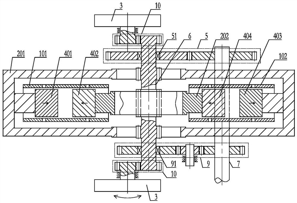
[0053] an engine such as figure 2 As shown, it includes a cylinder A101, a reciprocating structure A 201, a reciprocating structure B202, a cylinder B102, a moment of inertia body 3 and a rotating wheel 6, and a piston A 401 is set on the reciprocating structure A 201. A piston B 402 is arranged on the reciprocating structure B 202, and the piston A 401 and the piston B 402 are arranged in the cylinder A101 facing each other, and the reciprocating structure A 201 is arranged outside the cylinder A101. A gas distribution port is set on the cylinder A101, a piston C 403 is set on the reciprocating structure A 201, a piston D 404 is set on the reciprocating structure B 202, the piston C 403 and the piston D 404 The top is arranged in the cylinder B102, the reciprocating structure A 201 is arranged outside the cylinder B102, and a gas distribution port is set on the cylinder B102, the reciprocating structure A 201 and the reciprocating structure The body B 202 is set in reverse ...

Embodiment 3

[0067] an engine such as image 3 As shown, it includes a cylinder A101, a reciprocating structure A 201, a reciprocating structure B202, a moment of inertia body 3 and a rotating wheel 6. A piston A 401 is arranged on the reciprocating structure A 201, and a piston A 401 is set on the reciprocating structure A 201. A piston B 402 is set on the body B 202, the piston A 401 and the piston B 402 are arranged on top of each other in the cylinder A101, and the reciprocating structure A 201 is set in the cylinder A101 and passes through the piston B 402, a gas distribution port is set on the cylinder A101, the reciprocating structure A 201 and the reciprocating structure B 202 are set in reverse linkage through the transmission wheel 6, and the transmission wheel 6 and the rotating Inertia body 3 transmission settings, the transmission wheel 6 is set to the power shaft X 7 through the transmission route A5, the transmission wheel 6 is set to the power shaft X 7 through the transmis...


PUM


Abstract

The invention discloses an engine. The engine comprises an air cylinder A, a reciprocating movement structural body A, a reciprocating movement structural body B and rotary inertia bodies. A piston Aarranged on the reciprocating movement structural body A and a piston B arranged on the reciprocating movement structural body B are oppositely arranged in the air cylinder A. The reciprocating movement structural body A is arranged outside the air cylinder A. The reciprocating movement structural body A and the reciprocating movement structural body B are reversely linked through a transmission wheel, specifically, the transmission wheel and the rotary inertia bodies are arranged in a transmission mode. The transmission wheel conducts transmission on a power shaft X through a transmission path A and a transmission path B, an overrunning clutch A is arranged on the transmission path A, and an overrunning clutch B is arranged on the transmission path B. The transmission ratio of the transmission path A is a positive value, and the transmission ratio of the transmission path B is a negative value. The working directions of the overrunning clutches A and the overrunning clutches B are opposite. The transmission wheel which conducts transmission with the rotary inertia bodies and the transmission wheel which conducts transmission with the power shaft X are the same transmission wheel.The engine is not prone to flameout, is high in continuous working performance and can effectively break the limitation of a crankshaft-free air cylinder piston engine.

Description

technical field [0001] The invention relates to the field of thermal energy and power, in particular to an engine. Background technique [0002] The crankless cylinder piston engine has the characteristics of high efficiency, simple structure, less friction pairs, good environmental protection, and strong fuel diversity. However, its practical application has been limited. The fundamental reason is that this engine is easy to stall, and the output is not rotating power. It will be of great significance if a crankshaftless engine with high reliability and the ability to output rotational power can be invented. Therefore need to invent a kind of good novel engine of continuous duty. Contents of the invention [0003] In order to solve the above problems, the technical scheme proposed by the present invention is as follows: [0004] Scheme 1: An engine comprising a cylinder A, a reciprocating structure A, a reciprocating structure B, a moment of inertia body and a transmis...

Claims


Application Information

Patent Timeline
IPC IPC(8): F02B75/32F02B75/28F02B75/24
CPCF02B75/24F02B75/28F02B75/32
Inventor 靳北彪
Owner ENTROPY ZERO TECH LOGIC ENG GRP CO LTD
Why Eureka
Eureka Blog
Learn More