
A stall self-locking insurance structure for the suspended ship sling using the principle of centrifugal force

A centrifugal force and self-locking technology, applied in the direction of load suspension components, safety devices, balance weights, etc., can solve problems such as low safety factor, high safety factor, structural damage, etc., to ensure the safety of equipment and personnel, and improve the overall safety factor , the effect of reducing the probability of failure

Active Publication Date: 2022-02-01
东营胜华科贸有限公司
View PDF0 Cites 0 Cited by
  • Summary
  • Abstract
  • Description
  • Claims
  • Application Information

AI Technical Summary

Problems solved by technology

[0005] Aiming at the deficiencies of the prior art, the present invention provides a stall self-locking insurance structure for the suspension sling using the principle of centrifugal force, which has the advantages of self-locking safety for hook stall and high insurance coefficient, and solves the structural damage caused by the stall of the hook. low insurance factor

Method used


Image

  • A stall self-locking insurance structure for the suspended ship sling using the principle of centrifugal force
  • A stall self-locking insurance structure for the suspended ship sling using the principle of centrifugal force
  • A stall self-locking insurance structure for the suspended ship sling using the principle of centrifugal force

Examples


Embodiment Construction

[0024] The following will clearly and completely describe the technical solutions in the embodiments of the present invention with reference to the accompanying drawings in the embodiments of the present invention. Obviously, the described embodiments are only some, not all, embodiments of the present invention. Based on the embodiments of the present invention, all other embodiments obtained by persons of ordinary skill in the art without making creative efforts belong to the protection scope of the present invention.

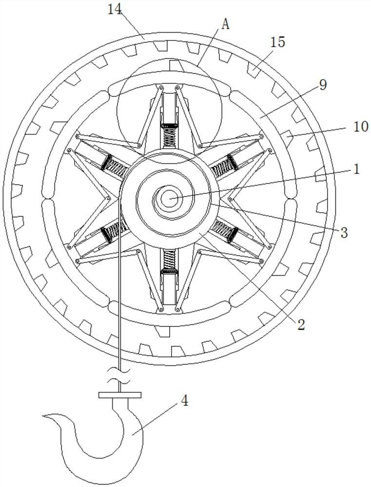
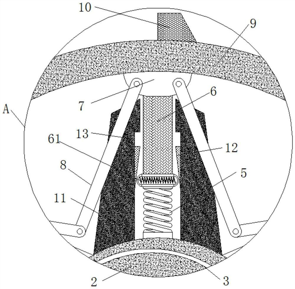
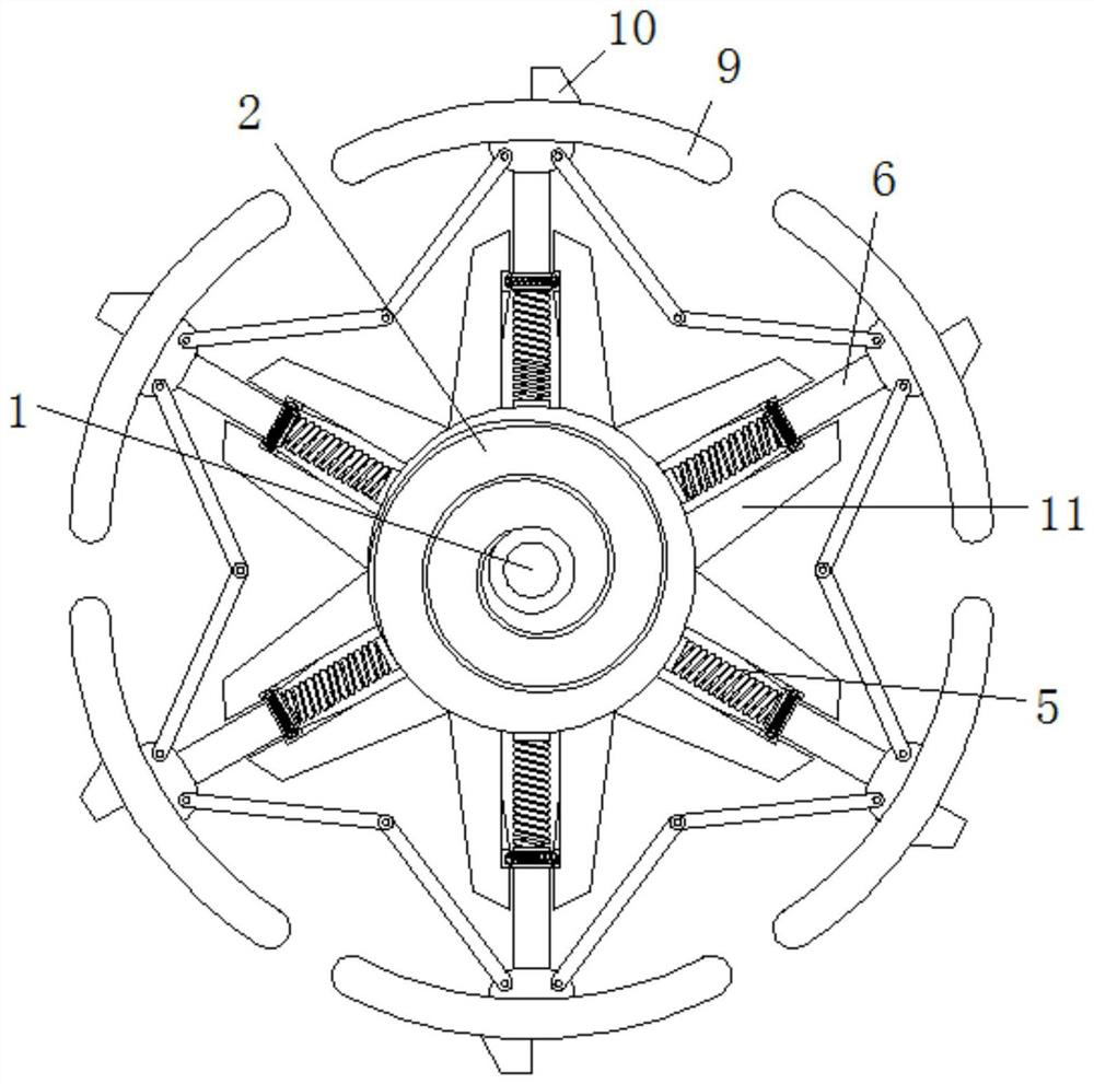
[0025] see Figure 1-4 , a stall self-locking insurance structure for a suspension sling utilizing the principle of centrifugal force, comprising a main shaft 1, the outer ring of the main shaft 1 is fixed and surrounded by a cable warehouse 2, a self-locking spring 5, a limit block 11 and a series of self-locking equipment settings There are six, and they are evenly distributed on the outer ring of the cable storehouse 2. Multiple self-locking structures wor...


PUM


Abstract

The invention relates to the technical field of ship hoisting, and discloses a stall self-locking insurance structure for a suspended ship sling using the principle of centrifugal force, including a main shaft, the outer ring of the main shaft is fixedly surrounded by a cable storehouse, and the interior of the cable storehouse is fixedly surrounded by a There is a suspension cable, the cable end of the suspension cable is fixedly connected with a suspension hook, the outer ring of the cable warehouse is fixedly connected with a self-locking spring, the upper end of the self-locking spring is fixedly connected with a self-locking rod, and the self-locking The inside of the rod is fixedly connected with a buckle spring, the upper end of the self-locking rod is fixedly connected with a connecting block, the side end of the connecting block is rotatably connected with a transmission rod, and the upper end of the connecting block is fixedly connected with a counterweight, so The upper surface of the counterweight is fixedly connected with a locking block. The stall self-locking insurance structure of the suspension sling using the principle of centrifugal force is achieved through the cooperation of self-locking springs, self-locking levers, buckle springs, connecting blocks, counterweights, upper locking blocks and lower locking blocks. Hook stall self-locking effect.

Description

technical field [0001] The invention relates to the technical field of ship hoisting, in particular to a stall self-locking insurance structure for a suspended ship sling using the principle of centrifugal force. Background technique [0002] A transport ship that carries heavy cargo and can be loaded and unloaded by its own equipment is also called a heavy cargo ship. With the development of society and economy, the water transport volume of heavy goods such as power generation equipment, chemical and oil refining equipment, drilling platforms, heat exchangers, nuclear reactors, locomotives, tugboats, barges, etc. is increasing day by day. These goods are too heavy and too large, or are restricted by port conditions, and cannot be transported by ordinary cargo ships. Since the end of the 1960s, various special heavy cargo carriers have emerged as the times require. [0003] In order to increase the lifting capacity of most cranes, the lifting height of the lifting equipme...

Claims


Application Information

Patent Timeline
Patent Type & Authority Patents(China)
IPC IPC(8): B66C1/34B66C15/00F16F15/28
CPCB66C1/34B66C15/00F16F15/28B66C2700/00
Inventor 颜肇宗
Owner 东营胜华科贸有限公司
Learn More