


Quick Research
Generate reliable direction feasibility study reports for your R&D in just a few steps.

Technical Q&A
Discover and master advanced knowledge NOW. Basics, ideas, possibilities, all at once.

Find Solutions
As an expert in R&D theories, this can generate solutions to your technical problems instantly.

Evaluate Feasibility
Analyze your overall solution with one click, know your potential R&D risks in advance.

Monitor Landscape
Get weekly tech updates, stay abreast of the latest tech innovations and key insights.
Distribution transformer terminal power consumption measuring circuit and distribution transformer terminal
A distribution transformer terminal and measurement circuit technology, which is applied in the measurement of electrical variables, electrical power, apparent power, etc., can solve the problems of poor accuracy, low efficiency, power consumption of the distribution transformer terminal and the need for repeated wiring, etc., to reduce the number of wiring , The effect of reducing power consumption measurement error
- Summary
- Abstract
- Description
- Claims
- Application Information
AI Technical Summary
Problems solved by technology
Method used
Image

Examples
Embodiment 1
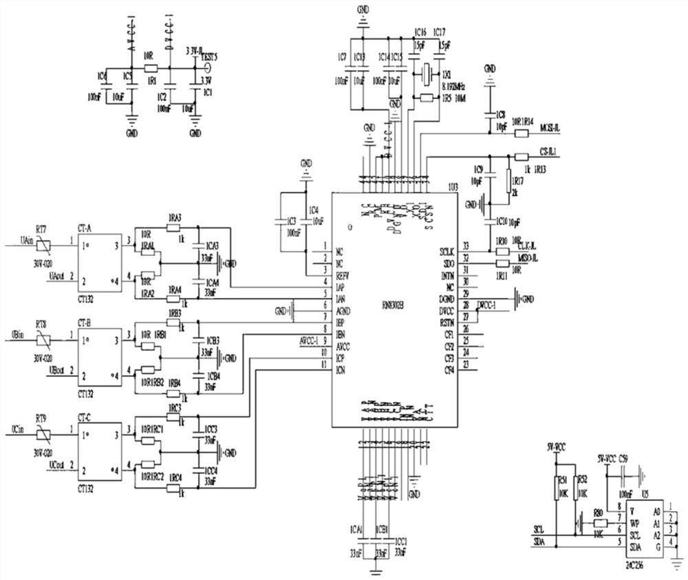
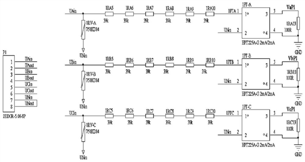
[0048] This embodiment provides a distribution transformer terminal power consumption measurement circuit, including a voltage power consumption measurement circuit. The voltage power consumption in this embodiment is the active power of the three phases of the distribution transformer terminal. The voltage and power consumption measurement circuit mainly includes a first metering chip, a current transformer for measuring the current of each phase, and a voltage transformer for measuring the voltage of each phase. Specifically, such as figure 1 As shown, it includes a first metering chip 1U3, and current transformers CT-A, CT-B, and CT-C respectively connected to corresponding phase lines of A, B, and C phases.
[0049] Taking the voltage and current detection of the phase line of the voltage A phase, and the calculation of the voltage power consumption as an example, the primary side of the current transformer CT-A samples the A phase connected to the three-phase voltage of t...
Embodiment 2
[0055] In this embodiment, a power consumption measurement circuit for measuring the current power consumption of the distribution transformer terminal, that is, the apparent power, is given, such as Figure 4 As shown, in this embodiment, the current power consumption measurement circuit includes a second voltage divider circuit and a second metering chip 2U3, the second voltage divider circuit samples the corresponding phase line connected to the three-phase current of the distribution transformer terminal, and the second The voltage divider circuit is also connected to the second metering chip 2U3; the second metering core calculates the current power consumption of each phase according to the collected voltage of each phase of the three-phase current of the distribution transformer terminal combined with the applied current; the second voltage divider circuit is connected to the second metering IAP pin, IAN pin, or IBP pin, IBN pin, or ICP pin, ICN pin of the chip. Figure...
Embodiment 3
[0061] The above-mentioned embodiment 1 of the power consumption measurement circuit of the distribution transformer terminal measures the active power of each phase of the distribution transformer terminal, while the embodiment 2 of the power consumption measurement circuit of the distribution transformer terminal measures the apparent power of each phase.
[0062] The difference between this embodiment and the above-mentioned embodiment 1 of the distribution transformer terminal power consumption measurement circuit and the embodiment 2 of the distribution transformer terminal power consumption measurement circuit is that in this embodiment, both the distribution transformer terminal power consumption measurement circuit embodiment 1 and the distribution transformer terminal power consumption measurement circuit are used. The circuit in Embodiment 2 of the terminal power consumption measurement circuit detects active power and apparent power.
[0063] Therefore, this embodime...
PUM
 Abstract
Description
Claims
Application Information
 - R&D Engineer
- R&D Manager
- IP Professional
- Industry Leading Data Capabilities
- Powerful AI technology
- Patent DNA Extraction
Browse by: Latest US Patents, China's latest patents, Technical Efficacy Thesaurus, Application Domain, Technology Topic, Popular Technical Reports.
© 2024 PatSnap. All rights reserved.Legal|Privacy policy|Modern Slavery Act Transparency Statement|Sitemap|About US| Contact US: help@patsnap.com