
Microsphere inner surface defect measurement method

A measurement method and inner surface technology, applied in the field of optical inspection, can solve problems such as defocusing of inner surface defects, and achieve the effect of avoiding installation and adjustment errors.

Active Publication Date: 2020-09-11
NANJING UNIV OF SCI & TECH
View PDF5 Cites 7 Cited by
  • Summary
  • Abstract
  • Description
  • Claims
  • Application Information

AI Technical Summary

Problems solved by technology

[0005] The object of the present invention is to provide a method for measuring defects on the inner surface of microspheres, which eliminates the problem of modulation of defects on the outer surface of the inner surface of microspheres The effect of defects, which solves the problem of out-of-focus defects on the inner surface when imaging on the outer surface

Method used


Image

  • Microsphere inner surface defect measurement method
  • Microsphere inner surface defect measurement method
  • Microsphere inner surface defect measurement method

Examples


Embodiment Construction

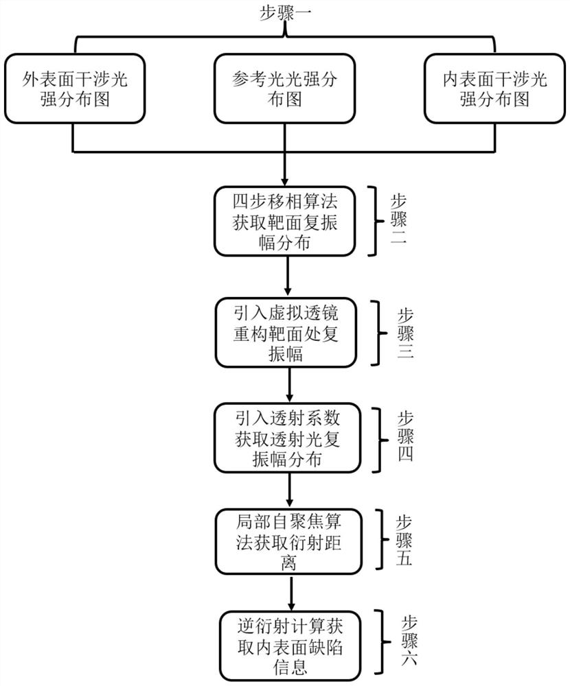
[0051] Such as figure 1 As shown, a method for measuring internal surface defects of microspheres, the specific steps are as follows:

[0052] Step 1: Use the microsphere inner surface defect measuring device to obtain the interference intensity map of the test light and the reference light on the outer surface of the microsphere, the interference intensity map of the test light and the reference light on the inner surface of the microsphere, and the light intensity distribution map of the reference light.

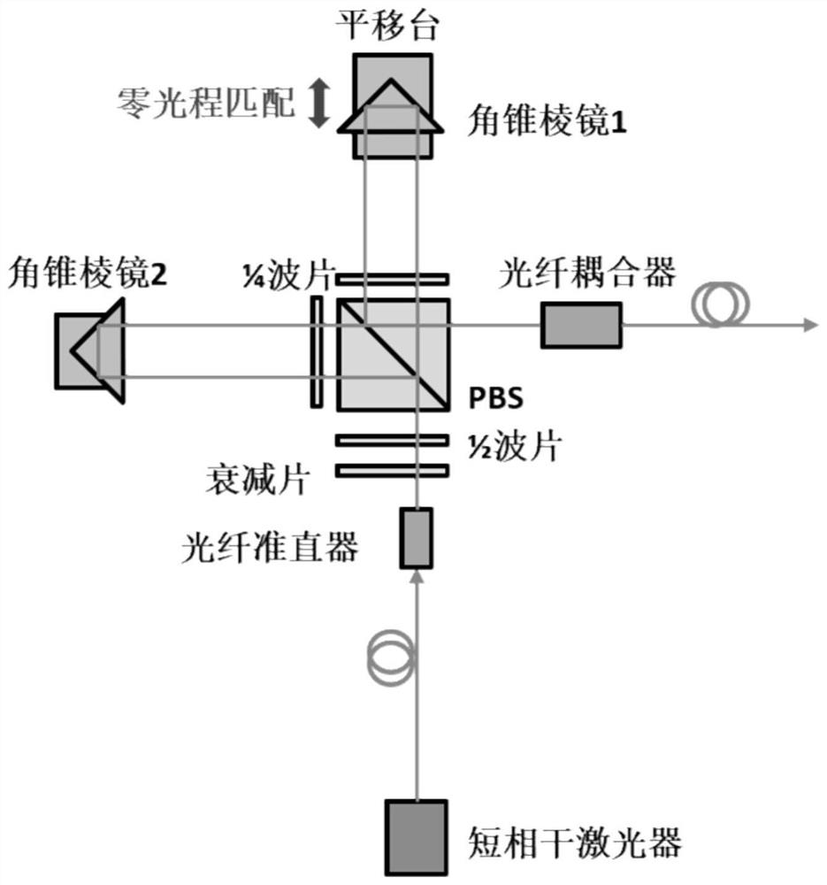
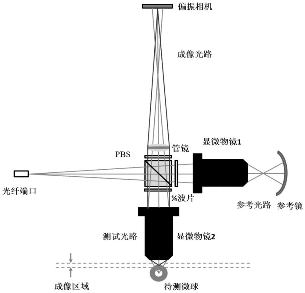
[0053] The microsphere inner surface defect measuring device includes two parts: a short-coherent light source module and a micro-interference imaging measurement module. Such as figure 2 As shown, the light emitted by the short-coherent laser in the short-coherent light source module passes through the attenuator and the 1 / 2 wave plate, where the 1 / 2 wave plate is used to adjust the amplitude ratio of the subsequent S light and P light, and then passes through the PBS polariz...


PUM


Abstract

The invention discloses a microsphere inner surface defect measurement method. The method comprises the following steps: acquiring an interference intensity graph of microsphere outer surface test light and reference light, an interference intensity graph of microsphere inner surface test light and reference light and a light intensity distribution graph of reference light; obtaining complex amplitude distribution of the outer surface interference light field and the inner surface interference light field; introducing a virtual lens for complex amplitude reconstruction to obtain complex amplitude distribution of the reconstructed outer surface interference light field and inner surface interference light field; converting the complex amplitude of the outer surface test light into transmission light to reconstruct the complex amplitude; obtaining an inner surface reconstruction complex amplitude after elimination and modulation; according to the diffraction distance, using reverse diffraction calculation to obtain diffraction surface complex amplitude distribution, and determining inner surface defect phase information. According to the invention, the virtual lens is introduced, diffraction calculation between curved surfaces is converted into diffraction calculation between planes, and the sampling problem caused by introduction of spherical phase is avoided.

Description

Technical field [0001] The invention belongs to the field of optical detection, and is specifically a method for measuring defects on the inner surface of microspheres. Background technique [0002] In the ICF experiment, multiple high-energy lasers directly or indirectly bombard the micro-target pellets to produce a fusion reaction. Micro-targets with diameters ranging from hundreds of microns to a few millimeters are one of the core devices of laser fusion. Any tiny defects on the inner surface of the target may cause Rayleigh-Taylor instability, which in turn will cause asymmetric compression and lead to The experimental efficiency is reduced, and even the serious consequences of target failure. [0003] In the internal surface defect measurement of the existing microscopic system, according to the surface detection method, it can be divided into: point detection method and surface detection method. In the spot detection method, Rivermore National Laboratory is the representat...

Claims


Application Information

Patent Timeline
IPC IPC(8): G01N21/88
CPCG01N21/88
Inventor 马骏淳秋垒李建欣朱日宏魏聪刘戴明
Owner NANJING UNIV OF SCI & TECH
Learn More