
Axial and vibration high-low cycle composite fatigue test device

A fatigue test, axial technology, applied in the field of mechanical tests, can solve the problems of difficult precise application and control of axial fatigue load, low vibration fatigue loading frequency, and difficult simulation of cantilever vibration conditions

Active Publication Date: 2020-09-11
AVIC BEIJING INST OF AERONAUTICAL MATERIALS
View PDF13 Cites 7 Cited by
  • Summary
  • Abstract
  • Description
  • Claims
  • Application Information

AI Technical Summary

Problems solved by technology

[0003] 1. The axial fatigue load is difficult to apply and control accurately;
[0004] 2. The vibration condition of the cantilever is difficult to simulate;
[0005] 3. The frequency of vibration fatigue loading is low, which cannot meet the needs of ultra-high cycle fatigue tests

Method used


Image

  • Axial and vibration high-low cycle composite fatigue test device
  • Axial and vibration high-low cycle composite fatigue test device
  • Axial and vibration high-low cycle composite fatigue test device

Examples


Embodiment Construction

[0020] In order to understand the purpose, technical solutions and advantages of the present invention more clearly, the present invention will be further described in detail below in conjunction with the accompanying drawings and embodiments.

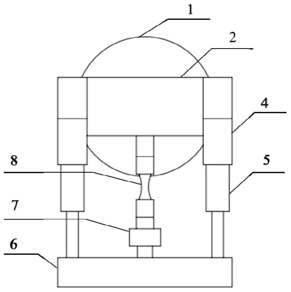
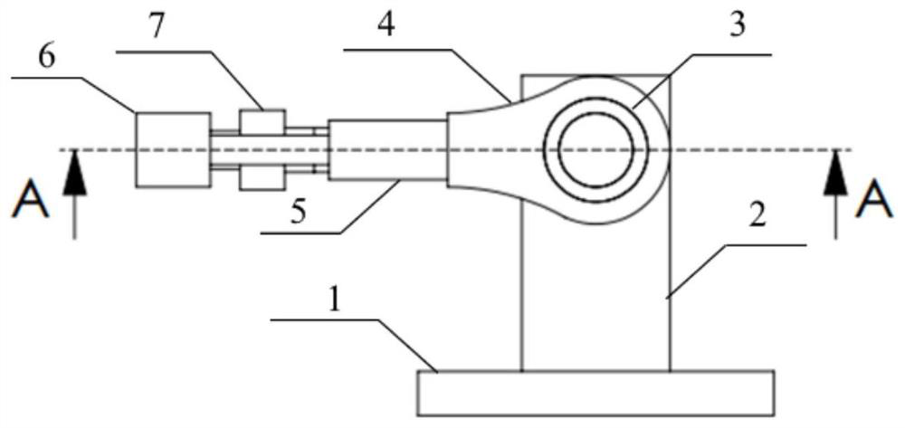
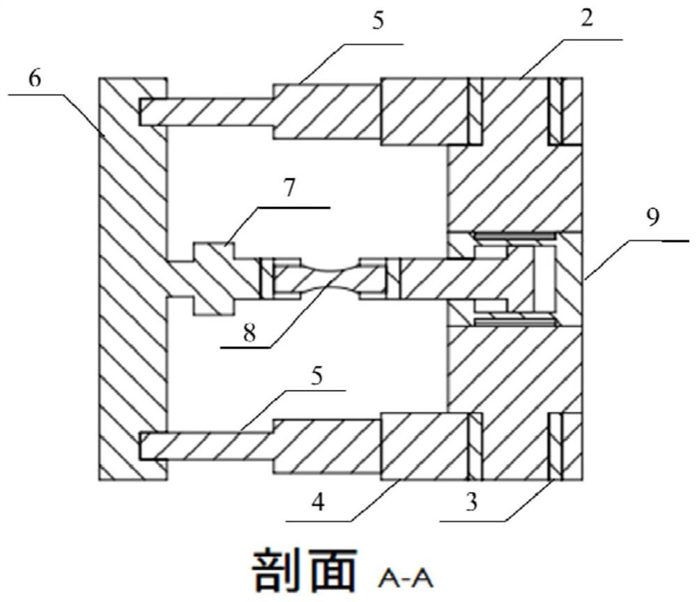
[0021] Figure 1-4 The structure of the composite fatigue test device of the axial direction and vibration high and low cycles of the present invention is illustrated. in addition, Figure 5 It is a schematic diagram of the installation of the device of the present invention on an electromagnetic vibrating table. see Figure 1-4 , the axial and vibration high and low cycle composite fatigue test device of the present invention includes a transition plate 1. During the test, the axial and vibration high and low cycle composite fatigue test device is rigidly installed on such as a vibration table, especially an electromagnetic vibration table, through the transition plate 1 On existing excitation equipment such as. The base 2 of the ...


PUM


Abstract

The invention relates to an axial and vibration high-low cycle composite fatigue test device. The device comprises a base (2) which is rigidly connected with excitation equipment through a transitionplate (1), cantilevers arranged on two sides of the base (2) are connected with connecting arms (4); one end of each of two connecting rods (5) is mounted on one connecting arm (4); a beam (6) is installed at the other end of each connecting rod; the beam (6), bearings (3) arranged on the two sides of the base (2), the connecting arms (4) and the connecting rods (5) form a load frame capable of smoothly rotating around cantilevers on the two sides of the base (2), a sample (8) and an axial force applying device (9) are connected to the symmetry axis of the load frame in series, and an axial force applying device (9) is fixed to the base (2). The axial force applying device of the test device can axially load the sample; when the excitation equipment excites at a resonance frequency, the load frame drives the sample to resonate, and the cantilever bending load generated by resonance is completely borne by the sample, so that the high-cycle vibration fatigue load is superposed on the low-cycle axial fatigue load.

Description

technical field [0001] The invention belongs to the technical field of mechanical tests, and in particular relates to a composite fatigue test device for axial and vibration high and low cycles. Background technique [0002] Aeroengine blades are subjected to both centrifugal and vibration loads during service. After the engine is started, the high-speed rotation of the blades produces huge centrifugal force, which belongs to low-cycle fatigue loads; the engine blades resonate due to the influence of airflow or structural vibration during operation, which belongs to high-cycle vibration fatigue loads. Therefore, the stress state of the engine blade in actual service is the superposition state of low cycle fatigue load and high cycle vibration fatigue load. According to the "General Specifications for Aeronautical Turbojet and Turbofan Engines" (GJB241A-2010), engine blades and materials need to be subjected to fatigue tests under coordinated loading of axial loads and high-...

Claims


Application Information

Patent Timeline
IPC IPC(8): G01M13/00G01N3/36G01N3/38
CPCG01M13/00G01N3/36G01N3/38G01N2203/0026G01N2203/0073
Inventor 陈新杨宪峰许巍何玉怀
Owner AVIC BEIJING INST OF AERONAUTICAL MATERIALS
Learn More