


Quick Research
Generate reliable direction feasibility study reports for your R&D in just a few steps.

Technical Q&A
Discover and master advanced knowledge NOW. Basics, ideas, possibilities, all at once.

Find Solutions
As an expert in R&D theories, this can generate solutions to your technical problems instantly.

Evaluate Feasibility
Analyze your overall solution with one click, know your potential R&D risks in advance.

Monitor Landscape
Get weekly tech updates, stay abreast of the latest tech innovations and key insights.
A non-clogging fixed submersible sewage pump
A fixed, non-clogging technology, applied in the direction of non-variable-capacity pumps, non-displacement pumps, pumps, etc., can solve the problems of accelerated sewage pump, sewage pump clogging, clogging, etc., to achieve easy control, clever design, small size Effect
- Summary
- Abstract
- Description
- Claims
- Application Information
AI Technical Summary
Problems solved by technology
Method used
Image

Examples
Embodiment 1
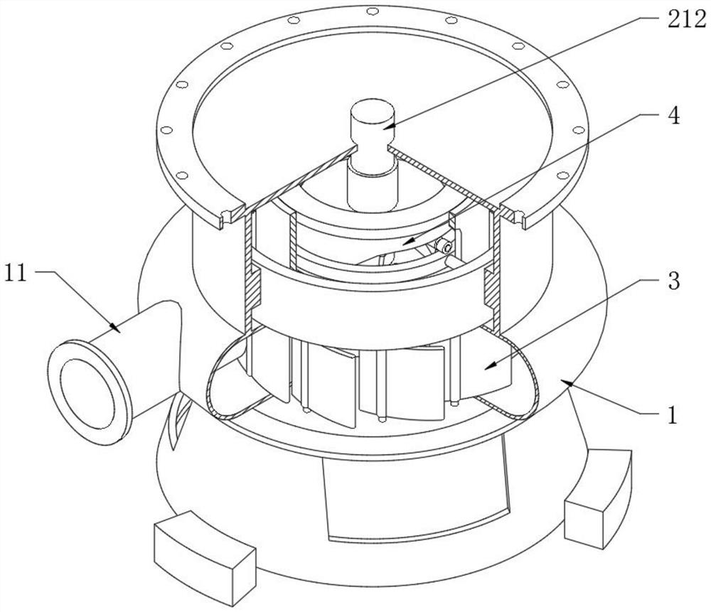
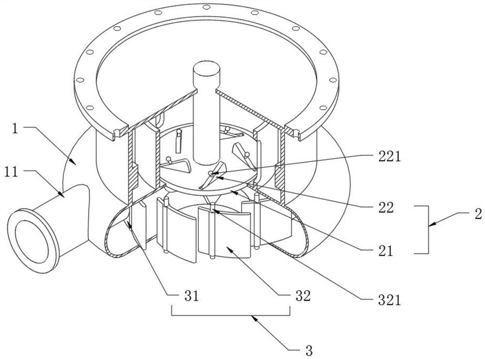
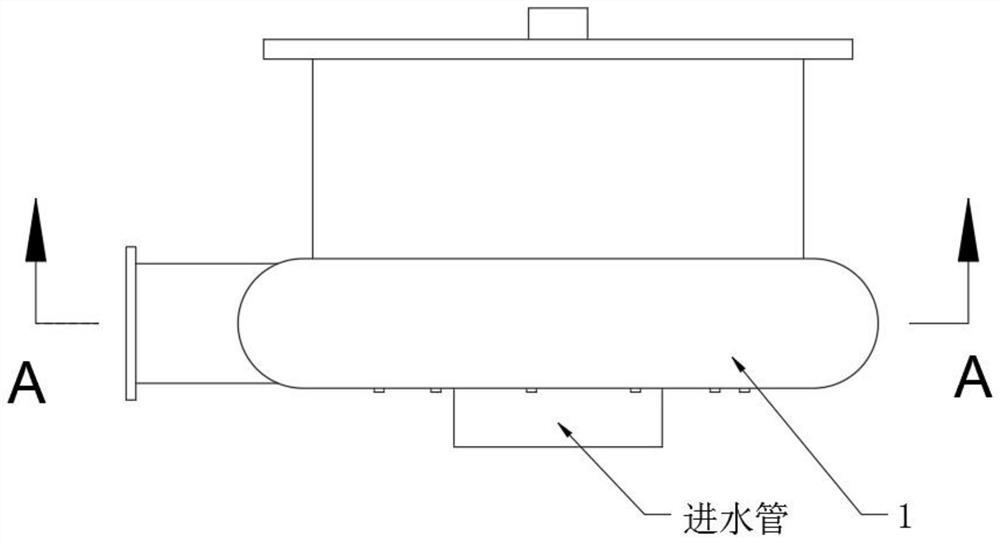
[0039] see Figure 1-7 , a non-clogging fixed submersible sewage pump, including a disc-shaped pump casing 1 and a sewage wheel 2, the bottom of the disc-shaped pump casing 1 is provided with a water inlet pipe, and the sewage wheel 2 rotates in the inner cavity of the disc-shaped pump casing 1 to turn the external The sewage is sucked into the disc-shaped pump casing 1 through the water inlet pipe, and the motor unit is installed on the upper part of the disc-shaped pump casing 1. The rotor on the motor unit is fixedly connected with the sewage wheel 2, and the supporting feet are installed on the lower part of the disc-shaped pump casing 1. Therefore, the combination of the above structures can constitute a complete sewage pump; this technical solution is to elaborate on the structure and cooperation of the disc-shaped pump casing 1 and the sewage wheel 2, and the outer wall of the disc-shaped pump casing 1 is provided with a sewage discharge pipe 11. A circular combination sl...
Embodiment 2
[0041] see Figure 6-12 Compared with Embodiment 1, the further description is that the linkage combination 4 includes a driving disc 41, a track sleeve 42, a return spring 43, a driving ring 44 and a driving sleeve 45. The middle part of the driving disc 41 is sleeved on the transmission shaft 212 and is axially Sliding fit, that is to say, the drive disc 41 can slide axially during the rotation of the drive shaft 212. The upper end surface of the disc-shaped pump casing 1 is fixed in the sleeve 15 with guide sleeves 16 and track sleeves 42 distributed coaxially. It is a T-shaped structure and is fixedly arranged on the top of the guide sleeve 16. The drive ring 44 is sleeved in the guide sleeve 16 and is located at the bottom of the track sleeve 42. It is worth noting that the inner diameter of the drive ring 44 is larger than the outer diameter of the lower end of the track sleeve 42. diameter, the return spring 43 is located at the bottom of the drive ring 44, and plays a ...
Embodiment 3
[0043] see Figure 13 The difference from Embodiment 1 is that the outer periphery of the disc-shaped pump casing 1 is provided with an arc-shaped notch 17, and the arc-shaped cover 5 matching the arc-shaped notch 17 is slidably connected in the circumferential direction. Slideways are set up on the periphery, and sliders are set up on the inner wall of the arc-shaped cover 5, so that the sliding arc-shaped cover 5 can realize the opening and closing of the arc-shaped gap 17. In embodiment 1, the blocked objects are thrown into the sewage collection In the cavity 13, when it is necessary to discharge the collected blockage, the handle on the sliding arc-shaped cover 5 can be used to scrape off the collected blockage with an external cleaning tool, so as to facilitate the discharge of the blockage.
[0044] Working principle: When in use, connect the top of the envelope 15 to the submersible motor unit through bolts, and fix the rotor on the motor unit to the drive shaft 212, t...
PUM
 Abstract
Description
Claims
Application Information
 - R&D Engineer
- R&D Manager
- IP Professional
- Industry Leading Data Capabilities
- Powerful AI technology
- Patent DNA Extraction
Browse by: Latest US Patents, China's latest patents, Technical Efficacy Thesaurus, Application Domain, Technology Topic, Popular Technical Reports.
© 2024 PatSnap. All rights reserved.Legal|Privacy policy|Modern Slavery Act Transparency Statement|Sitemap|About US| Contact US: help@patsnap.com