
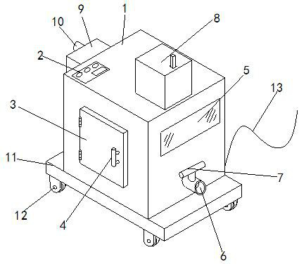
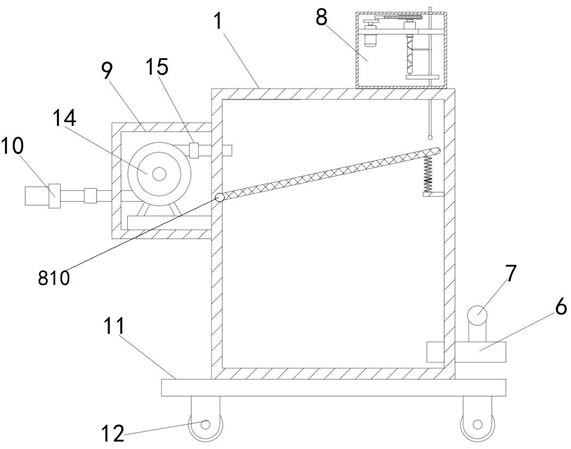
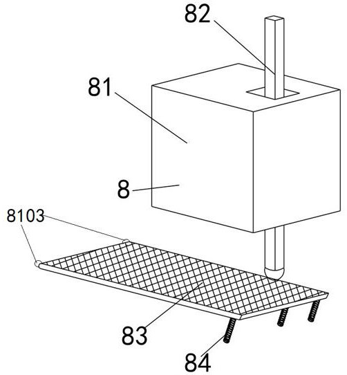
A waterproof drainage device for water conservancy construction

A water conservancy project and drainage device technology, applied in water supply devices, sewage removal, waterway systems, etc., can solve problems such as poor water filtration effect, inconvenient use, and blockage of drain outlets

Active Publication Date: 2021-02-09
南通远洋船舶配套有限公司
View PDF6 Cites 0 Cited by
  • Summary
  • Abstract
  • Description
  • Claims
  • Application Information

AI Technical Summary

Problems solved by technology

[0003] However, the new type of waterproof drainage device for water conservancy construction generally uses a water pump to pump water into and out of the body, and the solenoid valve is activated by the control switch to discharge the water through the drain. It is poor, and it is easy to cause blockage of the drain outlet during use, which affects work efficiency. At the same time, the traditional new type of waterproof drainage device for water conservancy construction has a poor driving effect on the drum, resulting in inconvenient use. The traditional filter screen is fixed. The drainage process The impact force of the medium water flow is large, which will directly impact the internal equipment of the drainage equipment and affect the service life of the equipment. During the drainage process, the water flow drawn in by the water pump forms a single parabola in the direction of the water flow inside the drainage body, which not only leads to Excessive local pressure will also lead to the accumulation of filtered debris somewhere on the filter plate, which will affect the drainage and filtration effect in the later stage
When the drainage device needs to replace the internal filter plate, the disassembly and assembly of the filter plate is more troublesome, and the later maintenance is inconvenient

Method used


Image

  • A waterproof drainage device for water conservancy construction
  • A waterproof drainage device for water conservancy construction
  • A waterproof drainage device for water conservancy construction

Examples


Embodiment Construction

[0032] The following will clearly and completely describe the technical solutions in the embodiments of the present invention with reference to the accompanying drawings in the embodiments of the present invention. Obviously, the described embodiments are only some of the embodiments of the present invention, not all of them. Based on the embodiments of the present invention, all other embodiments obtained by persons of ordinary skill in the art without making creative efforts belong to the protection scope of the present invention.

[0033] It should be noted that all directional indications (such as up, down, left, right, front, back...) in the embodiments of the present invention are only used to explain the relationship between the components in a certain posture (as shown in the figure). Relative positional relationship, movement conditions, etc., if the specific posture changes, the directional indication will also change accordingly.

[0034]In addition, in the present ...


PUM


Abstract

The invention specifically relates to a novel waterproof and drainage device for water conservancy construction, and belongs to the related field of waterproof and drainage for water conservancy construction. Including the body, control switch, dodge door, handle, observation window, drain outlet, auxiliary filter device and solenoid valve, the auxiliary filter device is set at the right end of the top of the body, the drive mechanism is activated by the control switch, and the drive mechanism drives the drum to rotate. Make the sliding rod drive the movable rod to reciprocate up and down, thereby driving the filter plate to move together, preventing debris from accumulating in a certain place on the filter plate, effectively improving the filtering effect of the water flow, and at the same time increasing the buffering effect through the spring, which can prevent water flow It has a direct impact on the interior of the drainage device and effectively improves the service life of the drainage device. By rotating the ball head to ensure the rotation, it is also a new type of waterproof drainage device for water conservancy construction that is more convenient for later maintenance and replacement.

Description

technical field [0001] The invention specifically relates to a novel waterproof and drainage device for water conservancy construction, and relates to the related field of waterproof and drainage for water conservancy construction. Background technique [0002] Water conservancy engineering is a project built to control and allocate natural surface water and groundwater to achieve the purpose of eliminating harm and rejuvenating profits. It is also called water engineering. Water is an indispensable and precious resource for human production and life, but its natural existence The state does not fully meet the needs of human beings. Only by building water conservancy projects can water flow be controlled, floods prevented, and water volume adjusted and distributed. During the construction of water conservancy projects, new waterproof and drainage devices for water conservancy project construction are required. [0003] However, the new waterproof and drainage devices for wat...

Claims


Application Information

Patent Timeline
Patent Type & Authority Patents(China)
IPC IPC(8): E03F1/00F04D1/00
CPCE03F1/00F04D1/00
Inventor 丁亮
Owner 南通远洋船舶配套有限公司
Learn More