
Warping machine yarn traction device

A traction device and warping machine technology, applied in warping machines, other manufacturing equipment/tools, textiles and paper making, etc. Guarantee the effect of humidification, avoid waste of water resources, and avoid waste of water resources

Inactive Publication Date: 2020-09-11
张姗姗
View PDF0 Cites 0 Cited by
  • Summary
  • Abstract
  • Description
  • Claims
  • Application Information

AI Technical Summary

Problems solved by technology

[0003] However, when the existing warping machines quickly wind up the yarn, it is easy to break because the yarn is too dry, thus affecting the winding efficiency of the warping machine, and at the same time, most of the existing warping machines are not equipped with a The device for removing excess lint makes the lint on the yarn easy to float in the air and affect the health of the staff. At the same time, it is easy to be mixed on the winding device of the warping machine, resulting in affecting the quality of the yarn after winding

Method used


Image

  • Warping machine yarn traction device
  • Warping machine yarn traction device
  • Warping machine yarn traction device

Examples


Embodiment Construction

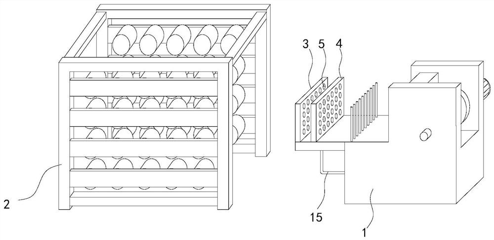
[0025] See Figure 1 to 7 , A schematic diagram of a plane structure and a schematic diagram of a three-dimensional structure of a yarn pulling device of a warping machine.

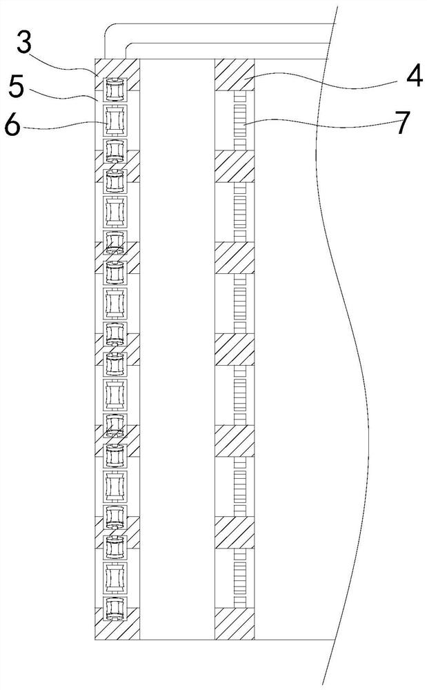
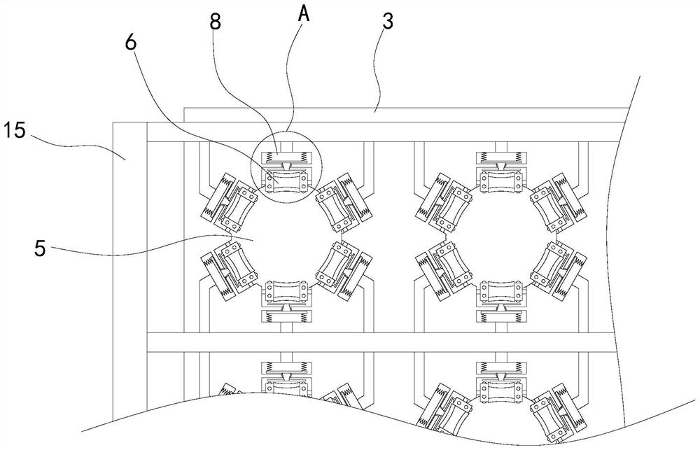
[0026] A yarn pulling device of a warping machine includes a warping winder 1, a warping humidifying device 3 is fixedly installed on the left side of the warping winder 1, and a humidifying wheel 6 is fixedly installed inside the warping humidifying device 3. A through hole 5 is opened inside the humidification device 3, and a warping and de-flocculation device 4 is fixedly installed on the right side of the warping humidification device 3.

[0027] In the specific implementation, the humidification wheel 6 is equidistantly arranged on the inner wall of the through hole 6 in the warping and humidification device 3, and the middle end of the humidification wheel 6 is arranged in an arc-shaped concave shape, so that when the yarn on the yarn creel 2 When the thread passes through the warping and humidification...


PUM


Abstract

The invention relates to the field of textile equipment, in particular to a warping machine yarn traction device. The warping machine yarn traction device comprises a warping winding machine, a warping humidifying device is fixedly installed on the left side of the warping winding machine, humidifying rotating wheels are fixedly installed inside the warping humidifying device, through holes are formed inside the warping humidifying device, and a warping flocculus removing device is fixedly installed on the right side of the warping humidifying device. The outer sides of the middle ends of thehumidifying rotating wheels are made of sponge so that water moving outwards in water storage cavities can be absorbed and extruded onto yarns after making contact with the yarns, water resource wasteis avoided, meanwhile, the yarns can be wrapped when the water makes contact with the yarns, the humidifying efficiency is improved, protruding strips are fixedly installed on the outer sides of themiddle ends of the humidifying rotating wheels, and the protruding strips are arranged in triangular shapes so that when the protruding strips make contact with the yarns, the counter-acting force onthe yarns can be improved, the efficiency that the yarns drive the humidifying rotating wheels to rotate is improved, then the humidifying effect of the yarn is improved, and the efficiency that driving blocks drive driving rods to move upwards can be improved due to the fact that the driving blocks are arranged in semi-spherical shapes.

Description

Technical field [0001] The invention relates to the field of textile equipment, in particular to a yarn pulling device of a warping machine. Background technique [0002] The textile process needs to go through six steps of warping, sizing, threading, weaving, finishing, and packing and storage. Among them, warping is a technological process in which a certain number of warp yarns are wound on a warp or weaving shaft in parallel according to a specified length and width. The warped warp yarns are used for sizing and drawing-in. The warping machine is a spinning machine. One of the more common equipment in the silk industry, it is used for warping production. The warping machine usually has a yarn creel, a pre-drawing device and a winding device with a warp beam. After the yarn is drawn from the yarn creel , The pre-drawing device is transported to the warp beam of the winding device, and then the warp beam is rotated to realize the winding of the yarn. The warped warp is used fo...

Claims


Application Information

Patent Timeline
Patent Type & Authority Applications(China)
IPC IPC(8): D02H3/00D02H13/00D06B1/14D02J7/00
CPCD02H3/00D02H13/00D02J7/00D06B1/14
Inventor 张姗姗
Owner 张姗姗
Learn More