


Quick Research
Generate reliable direction feasibility study reports for your R&D in just a few steps.

Technical Q&A
Discover and master advanced knowledge NOW. Basics, ideas, possibilities, all at once.

Find Solutions
As an expert in R&D theories, this can generate solutions to your technical problems instantly.

Evaluate Feasibility
Analyze your overall solution with one click, know your potential R&D risks in advance.

Monitor Landscape
Get weekly tech updates, stay abreast of the latest tech innovations and key insights.
High-temperature coal gas chilling chamber
A technology of chilling chamber and high temperature, which is applied in the fields of high-temperature gas chilling chamber, high-temperature gas containing carbon materials and gasification ash and slag. And other issues
- Summary
- Abstract
- Description
- Claims
- Application Information
AI Technical Summary
Problems solved by technology
Method used
Image

Examples
Embodiment 1
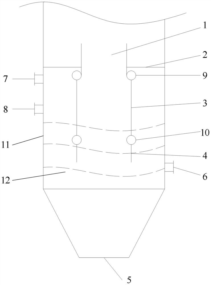
[0032] like figure 1 As shown, a high-temperature gas quenching chamber in this embodiment includes a quenching shell 11 and a water-cooled wall descending cylinder 3. A quenching chamber 12 is formed in the quenching shell 11, and the water-cooled wall descending cylinder 3 is arranged on the quenching shell. In the inner cavity of 11, the upper part of the water-cooled wall descending cylinder 3 is provided with a high-temperature gas inlet 1 for entering high-temperature gas and gasified ash, and the lower part of the water-cooled wall descending cylinder 3 extends into the quenching water bath of the quenching chamber 12, The bottom of the quenching chamber 12 is provided with a slag outlet 5, the upper side wall of the quenching shell is provided with a gas outlet 7, the lower side wall of the quenching chamber 12 is provided with a gray water outlet 6, and the water wall descending tube The annular space between 3 and the quenching shell 11 is the annular space of the qu...
Embodiment 2
[0035] like figure 1 As shown, a high-temperature gas quenching chamber in this embodiment includes all the technical features in Embodiment 1. In addition, it also includes a quenching water inlet 8, which is arranged on the upper part of the quenching shell On the side wall, the chilled water inlet 8 is located below the gas outlet 7.
[0036]A high-temperature gas quenching chamber in this embodiment, high-temperature gas and ash enter the water-cooled wall descending cylinder 3 from the high-temperature gas inlet 1, and enter the water bath at the lower part of the quenching chamber 12 under the protection of the water-cooled wall descending cylinder 3. In the water bath at the lower part of the water wall, the quenching and washing of high-temperature gas is completed, and the temperature of the gas after quenching and washing drops below 300°C, and the gas outlet 7 on the upper part of the quenching chamber 12 goes to the rear section; the quenching water is imported thr...
Embodiment 3
[0039] like figure 1 As shown, a high-temperature gas quenching chamber in this embodiment includes all the technical features in Embodiment 1. In addition, the water-cooled wall descending tube 3 is a vertical tube water-cooled wall or a spiral coil water-cooled wall; the water-cooled The boiler tubes of the wall drop tube 3 are connected by fins or directly connected; it also includes a flow guide tube 4, and the bottom of the water-cooled wall drop tube 3 is connected with a flow guide tube 4; There is a partition 2 between the combustion chamber of the gasifier, the partition 2 is located on the upper part of the annulus of the quenching chamber 12, and the partition 2 is located above the gas outlet 7; the cross section of the water-cooled wall descending tube 3 is circular or polygonal .
[0040] In some optional embodiments, the upper diameter of the water-cooled wall descending tube 3 is not equal to the lower diameter of the water-cooled wall descending tube 3 .
[...
PUM
 Abstract
Description
Claims
Application Information
 - R&D Engineer
- R&D Manager
- IP Professional
- Industry Leading Data Capabilities
- Powerful AI technology
- Patent DNA Extraction
Browse by: Latest US Patents, China's latest patents, Technical Efficacy Thesaurus, Application Domain, Technology Topic, Popular Technical Reports.
© 2024 PatSnap. All rights reserved.Legal|Privacy policy|Modern Slavery Act Transparency Statement|Sitemap|About US| Contact US: help@patsnap.com