
Automatic driving vehicle transverse motion control method and device and automatic driving vehicle

A technology of lateral motion and control method, which is applied in the direction of vehicle position/route/height control, non-electric variable control, control/regulation system, etc., which can solve the problems of occupying more computing resources and large amount of calculation, and reduce the amount of calculation , to ensure the effect of convergence

Active Publication Date: 2020-09-08
SANY SPECIAL PURPOSE VEHICLE CO LTD
View PDF5 Cites 13 Cited by
  • Summary
  • Abstract
  • Description
  • Claims
  • Application Information

AI Technical Summary

Problems solved by technology

[0002] The lateral control of autonomous driving vehicles calculates the expected steering command in real time based on the planned trajectory and vehicle positioning information of the upper layer, and controls the vehicle to drive along the target trajectory. At present, the optimal control parameter gain is generally obtained by solving the Riccati equation online, which requires a large amount of calculation. Requires more computing resources

Method used


Image

  • Automatic driving vehicle transverse motion control method and device and automatic driving vehicle
  • Automatic driving vehicle transverse motion control method and device and automatic driving vehicle
  • Automatic driving vehicle transverse motion control method and device and automatic driving vehicle

Examples


Embodiment 1

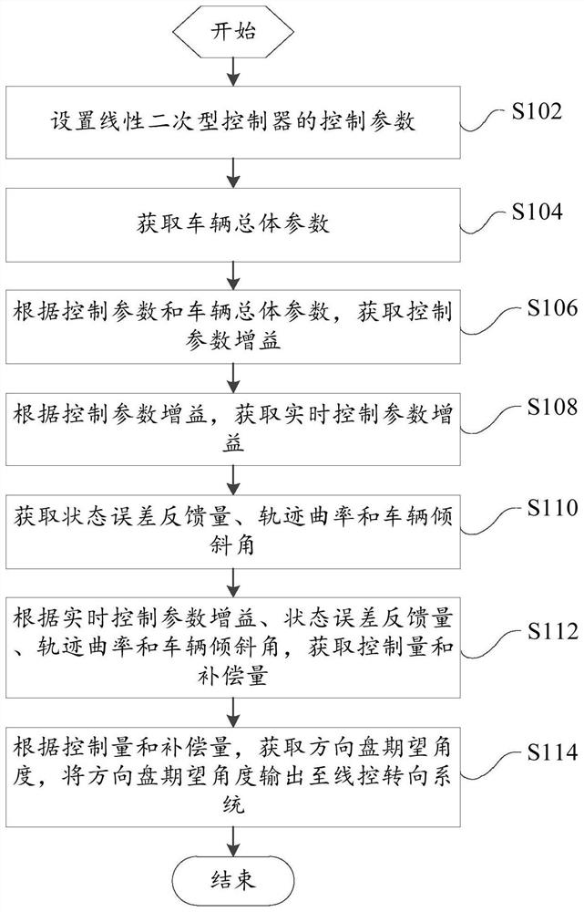
[0094] like figure 2 As shown, this embodiment provides a method for controlling lateral motion of an autonomous vehicle, including:

[0095] Step S102, setting the control parameters of the linear quadratic controller;

[0096] Step S104, acquiring overall parameters of the vehicle;

[0097] Step S106, according to the control parameter and the overall vehicle parameter, obtain the control parameter gain;

[0098] Step S108, according to the control parameter gain, obtain the real-time control parameter gain;

[0099] Step S110, obtaining state error feedback amount, trajectory curvature and vehicle inclination angle;

[0100] Step S112, obtaining the control amount and compensation amount according to the real-time control parameter gain, state error feedback amount, trajectory curvature and vehicle inclination angle;

[0101] Step S114, according to the control amount and the compensation amount, obtain the desired angle of the steering wheel, and output the desired an...

Embodiment 2

[0104] In addition to the technical features of the above embodiments, this embodiment further includes the following technical features.

[0105] In the above technical solution, setting the control parameters of the linear quadratic controller includes: the control parameters include the first weighting matrix Q and the second weighting matrix R, Q=diag[q 1 ,q 2 ,q 3 ,q 4 ], R=[r], where, q 1 ,q 2 ,q 3 ,q 4 and r are five control parameters respectively, q 2 ,q 4 and r are set to fixed values, q 1 ,q 3 Obtain according to the following formula:

[0106]

[0107]

[0108] Among them, q 1max for q 1 maximum value, q 1min for q 1 min, q 3max for q 3 maximum value, q 3min for q 3 Min, V x is the longitudinal speed of the vehicle, V 1 is the first speed threshold, V 2 is the second speed threshold.

[0109] In this embodiment, q2, q4, and r are set as fixed values, only for q1, q3 according to the vehicle speed V x Perform parameter linear adjustment,...

Embodiment 3

[0111] In addition to the technical features of the above embodiments, this embodiment further includes the following technical features.

[0112] According to the control parameters and the overall parameters of the vehicle, the control parameter gain is obtained, including: the control parameter gain is obtained by the following formula:

[0113]

[0114]

[0115] k 14 =[k 14(1) , k 14(2) , k 14(3) , k 14(4) ]

[0116] k 14 =lqr(A,B,Q,R)

[0117] k 1 =k 14(1)

[0118] k 2 =k 14(2)

[0119] k 3 =k 14(3)

[0120] k 4 =k 14(4)

[0121] Among them, m is the mass of the whole vehicle, I z is the moment of inertia of the vehicle around the vertical direction, l f is the distance from the front axle of the vehicle to the center of mass, l r is the distance from the rear axle of the vehicle to the center of mass, C f is the cornering stiffness of the front wheel, C r is the cornering stiffness of the rear wheel, V x is the longitudinal speed of the vehi...


PUM


Abstract

The invention provides an automatic driving vehicle transverse motion control method and device and an automatic driving vehicle. The automatic driving vehicle transverse motion control method comprises the steps: setting control parameters of a linear quadratic controller; obtaining vehicle overall parameters; according to the control parameters and the vehicle overall parameters, acquiring a control parameter gain; according to control parameter gain, acquiring a real-time control parameter gain; acquiring a state error feedback quantity, a track curvature and a vehicle inclination angle; acquiring a control quantity and a compensation quantity according to the real-time control parameter gain, the state error feedback quantity, the track curvature and the vehicle inclination angle; acquiring a steering wheel expected angle according to the control quantity and the compensation quantity; and outputting the steering wheel expected angle to a steer-by-wire system. According to the method, the transverse motion static-error-free optimal control of the automatic driving vehicle can be realized, the calculated amount is greatly reduced, the convergence of the optimal control gain is ensured, and the expected driving track is tracked with high reliability and high precision.

Description

technical field [0001] The present invention relates to the technical field of automatic driving vehicles, in particular to a method and device for controlling the lateral motion of the automatic driving vehicle and the automatic driving vehicle. Background technique [0002] The lateral control of the autonomous vehicle calculates the expected steering command in real time based on the planned trajectory and vehicle positioning information of the upper layer, and controls the vehicle to drive along the target trajectory. At present, the optimal control parameter gain is generally obtained by solving the Riccati equation online, which requires a large amount of calculation. It requires more computing resources. Contents of the invention [0003] The present invention aims to solve or improve at least one of the above technical problems. [0004] Therefore, the first object of the present invention is to provide a method for controlling lateral motion of an automatic drivi...

Claims


Application Information

Patent Timeline
Patent Type & Authority Applications(China)
IPC IPC(8): G05D1/02
CPCG05D1/0223G05D1/021B62D15/025
Inventor 文宝贺志国
Owner SANY SPECIAL PURPOSE VEHICLE CO LTD
Learn More