SLS-based metal surface crack detection system

A crack detection and metal surface technology, applied in measuring devices, processing response signals of detection, and analyzing solids using sonic/ultrasonic/infrasonic waves, etc. People's life safety and other issues, to achieve good industrial application prospects, accurate results, and intuitive detection results

Pending Publication Date: 2020-09-04
SHANGHAI UNIV OF ENG SCI
View PDF5 Cites 3 Cited by
  • Summary
  • Abstract
  • Description
  • Claims
  • Application Information

AI Technical Summary

Problems solved by technology

[0002] With the development of industrial modernization, metal parts are widely used in many important fields such as aerospace, energy and chemical industry, transportation, weaponry, production equipment, etc. Metal parts will be subjected to high temperature, high pressure, high load and corrosion during their service Harsh environmental influences such as radiation and radiation will cause defects such as cracks on the surface of metal parts. If the defects cannot be identified in a timely and effective manner and necessary measures are taken, the defects will further develop and eventually lead to the failure of the parts
The failure of metal parts seriously reduces the stability and reliability of the equipment, and may even lead to highly dangerous and destructive accidents, resulting in huge economic loss and endangering people's lives

Method used


Image

  • SLS-based metal surface crack detection system
  • SLS-based metal surface crack detection system
  • SLS-based metal surface crack detection system

Examples


Embodiment Construction

[0027] The present invention will be described in detail below in conjunction with the accompanying drawings and specific embodiments. This embodiment is carried out on the premise of the technical solution of the present invention, and detailed implementation and specific operation process are given, but the protection scope of the present invention is not limited to the following embodiments.

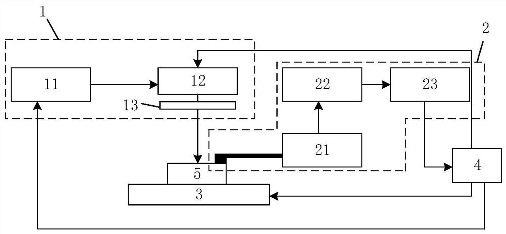
[0028] Such as figure 1 As shown, this embodiment discloses a metal surface crack detection system based on SLS, including a transmitting module 1 , a receiving module 2 , a three-dimensional mobile platform 3 and a control module 4 .

[0029] The measured workpiece 5 is placed on the three-dimensional mobile platform 3 to realize the three-axis movement of the measured workpiece 5 and the focusing and calibration of the measured workpiece 5 relative to the transmitting module 1 and the receiving module 2 .

[0030] The transmitting module 1 includes a high-frequency fiber optic puls...


PUM

PropertyMeasurementUnit
diameteraaaaaaaaaa
frequencyaaaaaaaaaa

Abstract

The invention relates to an SLS-based metal surface crack detection system, which comprises a transmitting module, a receiving module, a three-dimensional mobile platform and a control module, and ischaracterized in that a detected workpiece is placed on the three-dimensional mobile platform; the transmitting module comprises a high-frequency optical fiber pulse ultrasonic laser, a scanning galvanometer mechanism and a gathering mirror, and the high-frequency optical fiber pulse ultrasonic laser excites a beam of pulse ultrasonic laser to be reflected by the scanning galvanometer mechanism and then excited on a measured workpiece through the gathering mirror; the receiving module comprises a plurality of piezoelectric sensors, a charge amplifier and a high-speed data acquisition card; thepiezoelectric sensors are arranged around the surface of a measured workpiece; signals acquired by the piezoelectric sensors are connected with the high-speed data acquisition card through the chargeamplifier to complete real-time acquisition of the signals. Compared with the prior art, the method has the advantage that the metal surface cracks can be accurately and efficiently detected withoutdamage.

Description

technical field [0001] The invention relates to the field of non-destructive detection of metal surface cracks, in particular to an SLS-based metal surface crack detection system. Background technique [0002] With the development of industrial modernization, metal parts are widely used in many important fields such as aerospace, energy and chemical industry, transportation, weaponry, production equipment, etc. Metal parts will be subjected to high temperature, high pressure, high load and corrosion during their service Harsh environmental influences such as radiation and radiation will cause defects such as cracks on the surface of metal parts. If the defects cannot be identified in a timely and effective manner and necessary measures are taken, the defects will further develop and eventually lead to the failure of the parts. The failure of metal parts seriously reduces the stability and reliability of equipment, and may even lead to highly dangerous and destructive acciden...

Claims


Application Information

Patent Timeline
Patent Type & Authority Applications(China)
IPC IPC(8): G01N29/06G01N29/24G01N29/26G01N29/44G01N21/17
CPCG01N29/069G01N29/2418G01N29/2437G01N29/26G01N29/44G01N21/1702G01N2021/1706G01N2021/1708G01N2291/0234G01N2291/0289G01N2291/106G01N2291/263
Inventor 张兴媛宋大成周虹高锋陈超
Owner SHANGHAI UNIV OF ENG SCI
Why Eureka
Try Eureka