
Throttling device, refrigerant circulating system and dehumidifier

A technology of throttling device and refrigerant, applied in the fields of throttling device, refrigerant circulation system and dehumidifier, can solve the problem of large loss of compressor, and achieve the effect of reducing loss, realizing power regulation and prolonging service life

Pending Publication Date: 2020-09-04
QINGDAO HAIER AIR CONDITIONER GENERAL CORP LTD +1
View PDF0 Cites 0 Cited by
  • Summary
  • Abstract
  • Description
  • Claims
  • Application Information

AI Technical Summary

Problems solved by technology

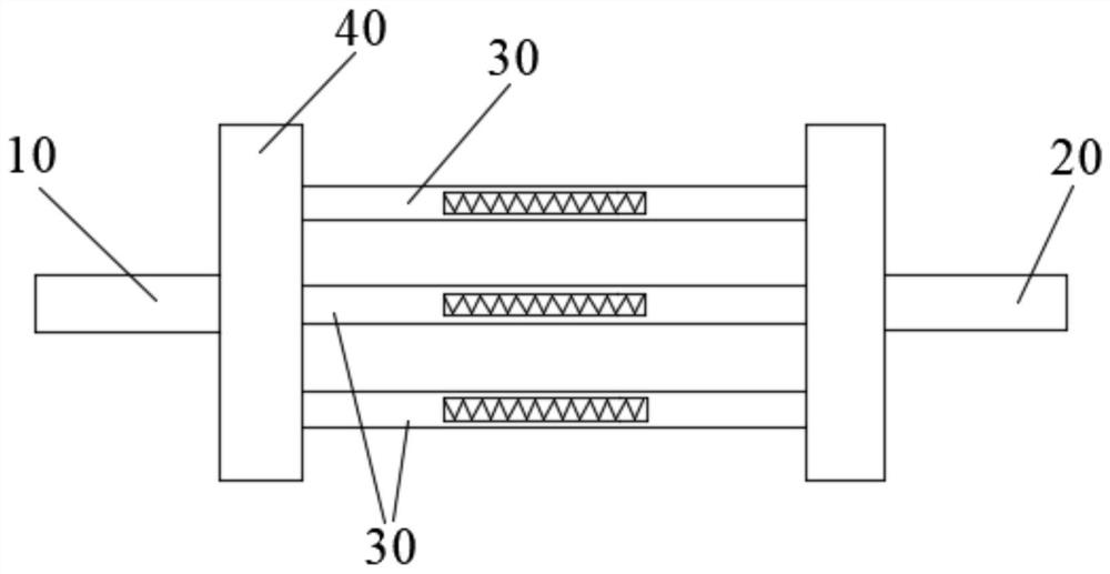
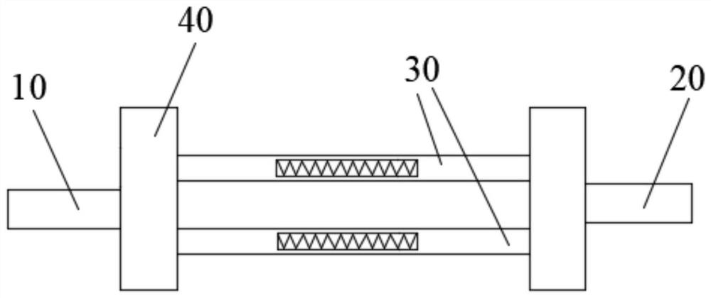
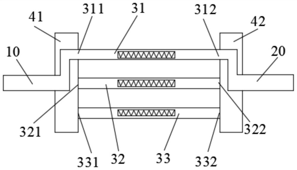
[0007] Embodiments of the present disclosure provide a throttling device, a refrigerant circulation system, and a dehumidifier to solve the problem that the compressor is frequently started and stopped during the dehumidification process of a fixed-frequency dehumidifier, resulting in a large loss of the compressor.

Method used


Image

  • Throttling device, refrigerant circulating system and dehumidifier
  • Throttling device, refrigerant circulating system and dehumidifier
  • Throttling device, refrigerant circulating system and dehumidifier

Examples


Embodiment Construction

[0024] In order to understand the characteristics and technical content of the embodiments of the present disclosure in more detail, the implementation of the embodiments of the present disclosure will be described in detail below in conjunction with the accompanying drawings. The attached drawings are only for reference and description, and are not intended to limit the embodiments of the present disclosure. In the following technical description, for purposes of explanation, numerous details are set forth in order to provide a thorough understanding of the disclosed embodiments. However, one or more embodiments may be practiced without these details. In other instances, well-known structures and devices may be shown simplified in order to simplify the drawings.

[0025] The terms "first", "second" and the like in the description and claims of the embodiments of the present disclosure and the above drawings are used to distinguish similar objects, and are not necessarily used...


PUM


Abstract

The invention relates to the technical field of electrical equipment, and discloses a throttling device. The throttling device comprises a liquid inlet end, a liquid outlet end, a plurality of throttling branches and a conversion valve; the multiple throttling branches are arranged between the liquid inlet end and the liquid outlet end, and the throttling flux of each throttling branch is different; and the conversion valve is arranged to be controlled to communicate at least one throttling branch with the liquid inlet end and the liquid outlet end. According to the throttling device, the multiple throttling branches with different throttling fluxes are arranged in the throttling device, and then the throttling branches communicating with a refrigerant pipeline are switched through the conversion valve; and at least one throttling branch communicating with the liquid inlet end and the liquid outlet end is switched, so that the throttling flux between the liquid inlet end and the liquidoutlet end of the throttling device is adjusted, then the power adjustment of a refrigerant circulating system is realized, the starting and stopping frequency of a compressor is reduced, the loss ofthe compressor caused by starting and stopping is reduced, and the service life of the compressor is prolonged. The invention further discloses the refrigerant circulating system and a dehumidifier.

Description

technical field [0001] The present application relates to the technical field of electrical equipment, for example, to a throttling device, a refrigerant circulation system and a dehumidifier. Background technique [0002] With the continuous improvement of people's living standards, dehumidifiers have gradually expanded from commercial use to household use, becoming an indispensable household appliance. [0003] At present, most household dehumidifiers are fixed-frequency dehumidifiers, which are composed of a casing, a compressor, a heat exchanger, and a fan. , so that the heat exchanger exchanges heat with the humid air, so that the water vapor in the humid air condenses into water, thereby reducing the water content in the air. [0004] In the process of implementing the embodiments of the present disclosure, it is found that at least the following problems exist in related technologies: [0005] Since the dehumidification power of the fixed-frequency dehumidifier is c...

Claims


Application Information

Patent Timeline
Patent Type & Authority Applications(China)
IPC IPC(8): F25B41/06F25B41/04F24F3/14F25B41/20F25B41/34F25B41/37
CPCF24F3/14F24F2003/1446
Inventor 张玲玲张振富王宜金
Owner QINGDAO HAIER AIR CONDITIONER GENERAL CORP LTD
Learn More