
Container turnover lifting appliance

A container and spreader technology, applied in the directions of transportation and packaging, load hanging components, etc., can solve the problems of low work efficiency, large contact space, environmental pollution, etc., and achieve the effect of improving efficiency and reducing load

Pending Publication Date: 2020-09-04
保定奥发吊索具制造有限公司
View PDF0 Cites 6 Cited by
  • Summary
  • Abstract
  • Description
  • Claims
  • Application Information

AI Technical Summary

Problems solved by technology

[0003] Among them, when loading and unloading bulk cargo containers, the cargo needs to be unloaded out of the box through the container door first, and then the cargo is stacked on the material pile or a predetermined position with grabs, transport belts and other machinery. Not only the work efficiency is low, but also the cargo and The external contact time is long and the contact space is large, which will cause greater pollution to the environment, especially for loading and unloading bulk cargo with radioactive ore, the pollution to the environment is more serious, so there is an urgent need for a container turning spreader with higher efficiency

Method used


Image

  • Container turnover lifting appliance
  • Container turnover lifting appliance
  • Container turnover lifting appliance

Examples


Embodiment 1

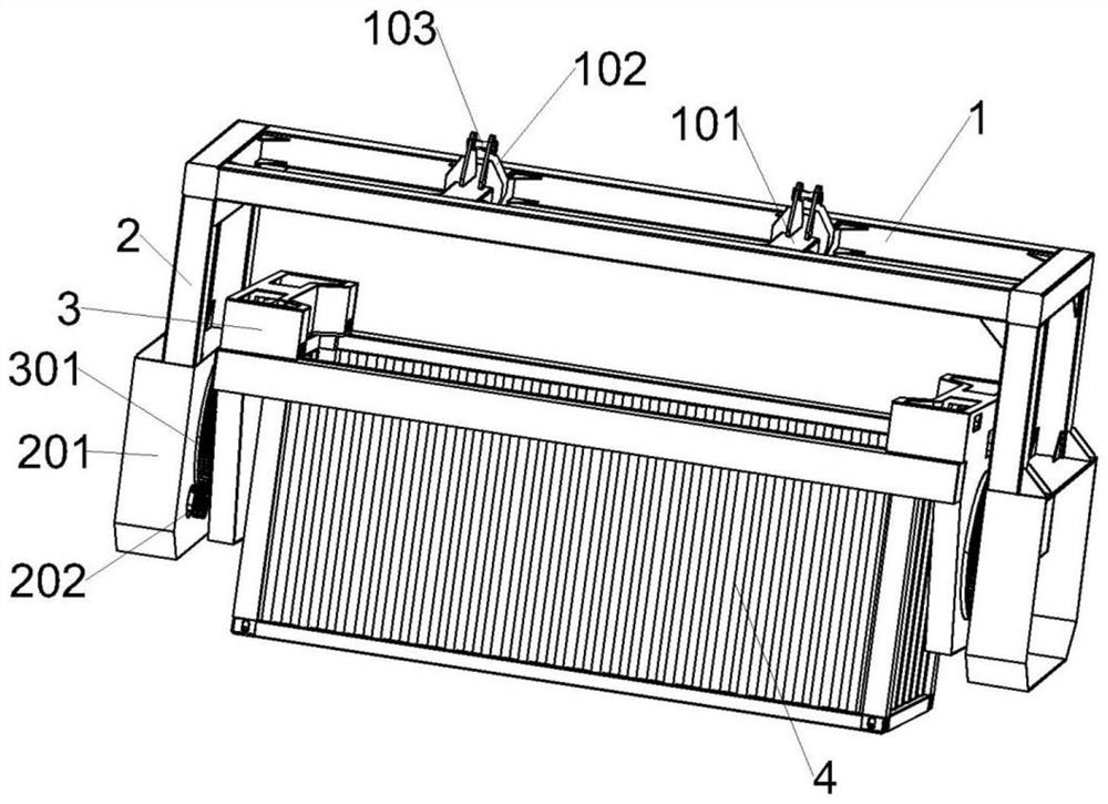
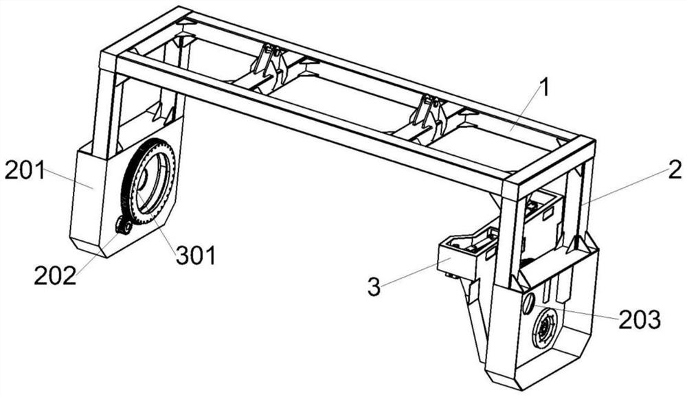
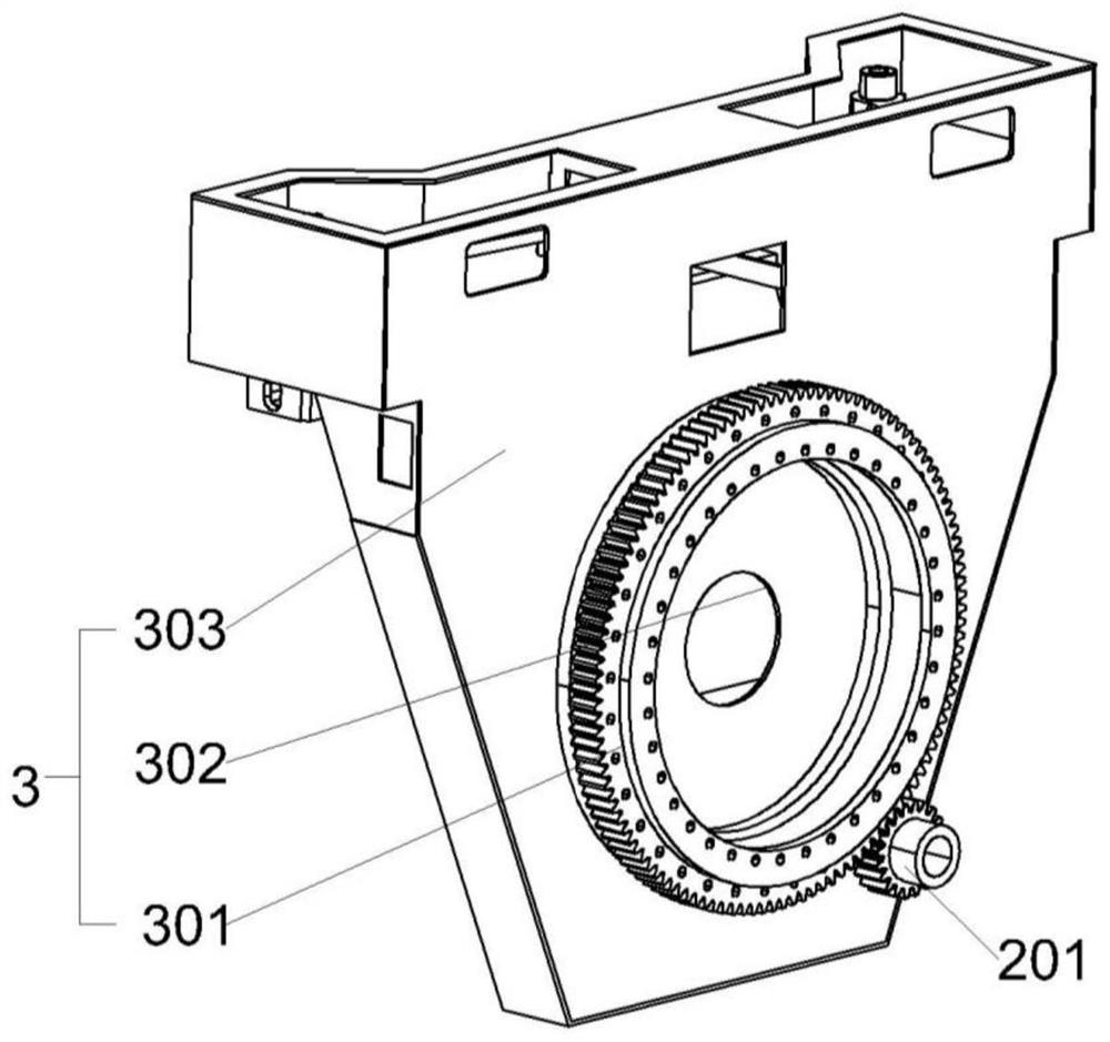
[0033] refer to Figure 1-7 As shown, this embodiment provides a container overturning spreader, including a container 4, a beam 1, a hook assembly fixedly arranged in the middle of the beam 1, a longitudinal beam 2 symmetrically fixed at both ends of the beam 1, and symmetrically arranged inside the longitudinal beam 2. The locking turning mechanism 3 and the driving mechanism that makes the locking turning mechanism 3 rotate, the driving mechanism is fixed on the bottom of the longitudinal beam 2, and the locking turning mechanism 3 is engaged with the driving mechanism. The lifting function of the container 4 is realized by the hook assembly, the container 4 and the spreader are locked by locking the turning mechanism 3, and the turning mechanism 3 is turned over by the driving mechanism to drive the container 4 to realize the turning function.

[0034] In a further optimized solution, the locking and turning mechanism 3 includes a first housing 303, a large gear 301 fixed ...

Embodiment 2

[0045] refer to Figure 8-11 As shown, the difference between the overturning spreader of this embodiment and the first embodiment is that the driving mechanism also includes a fixed block 3011 fixed on the side of the large gear 301, and the second housing 201 is provided with a space for making the fixed block 3011 move. slot 2011, a first pulley 2012 is fixed on the side of the second casing 201 close to the drive motor, a cylinder 2013 is fixed on the side of the second casing 201 away from the step-off groove 2011, and a second pulley 2014 is rotatably connected to the output shaft of the cylinder 2013. The top left of the cylinder 2013 is provided with a fixed rod 2015, the cylinder body of the cylinder 2013 is fixedly connected with the second housing 201, the fixed rod 2015 is fixedly connected with the second housing 201, the first pulley 2012 is arranged under the fixed block 3011, and the fixed block 2011 is fixed One end of the wire rope 8 is connected, the wire ro...


PUM


Abstract

The invention relates to the field of lifting equipment, in particular to a container turnover lifting appliance. The container turnover lifting appliance comprises a container, a transverse beam, a lifting hook assembly fixedly arranged in the middle of the transverse beam, longitudinal beams symmetrically fixed at two ends of the transverse beam, locking turnover mechanisms symmetrically arranged on the inner sides of the longitudinal beams, and driving mechanisms for driving the locking turnover mechanisms to rotate, wherein the driving mechanisms are fixed at the bottoms of the longitudinal beams, and the locking turnover mechanisms are in meshing connection with the driving mechanisms. The container turnover lifting appliance directly achieves turnover unloading in the lifting processof the bulk container, thereby improving the goods circulation efficiency.

Description

technical field [0001] The invention relates to the field of hoisting equipment, in particular to a container overturning spreader. Background technique [0002] my country is a large economic country with an annual port throughput of hundreds of millions of tons. Containers are the most used in port transportation. Containers are divided into dry cargo containers, bulk containers, liquid cargo containers, and reefer containers. [0003] Among them, when loading and unloading bulk cargo containers, the cargo needs to be unloaded out of the box through the container door first, and then the cargo is stacked on the material pile or a predetermined position with grabs, transport belts and other machinery. Not only the work efficiency is low, but also the cargo and The long time of contact with the outside world and the large contact space will cause greater pollution to the environment, especially for loading and unloading bulk cargo with radioactive ore, the pollution to the e...

Claims


Application Information

Patent Timeline
Patent Type & Authority Applications(China)
IPC IPC(8): B66C1/42B66C13/08
CPCB66C1/42B66C1/427B66C13/08
Inventor 米伟于海洋米欢任神通张康
Owner 保定奥发吊索具制造有限公司
Learn More