


Quick Research
Generate reliable direction feasibility study reports for your R&D in just a few steps.

Technical Q&A
Discover and master advanced knowledge NOW. Basics, ideas, possibilities, all at once.

Find Solutions
As an expert in R&D theories, this can generate solutions to your technical problems instantly.

Evaluate Feasibility
Analyze your overall solution with one click, know your potential R&D risks in advance.

Monitor Landscape
Get weekly tech updates, stay abreast of the latest tech innovations and key insights.
Construction waste screening device
A technology of construction waste and sieve cylinder, applied in the direction of filter screen, solid separation, grille, etc., can solve the problems of high wear rate of equipment, easy blockage in the holes of the sieve cylinder, time-consuming screening, etc., and achieve the effect of high wear rate of equipment
- Summary
- Abstract
- Description
- Claims
- Application Information
AI Technical Summary
Problems solved by technology
Method used
Image

Examples
no. 1 example
[0028] Such as Figure 1-Figure 4 As shown, the present invention provides a kind of technical scheme of construction waste screening:
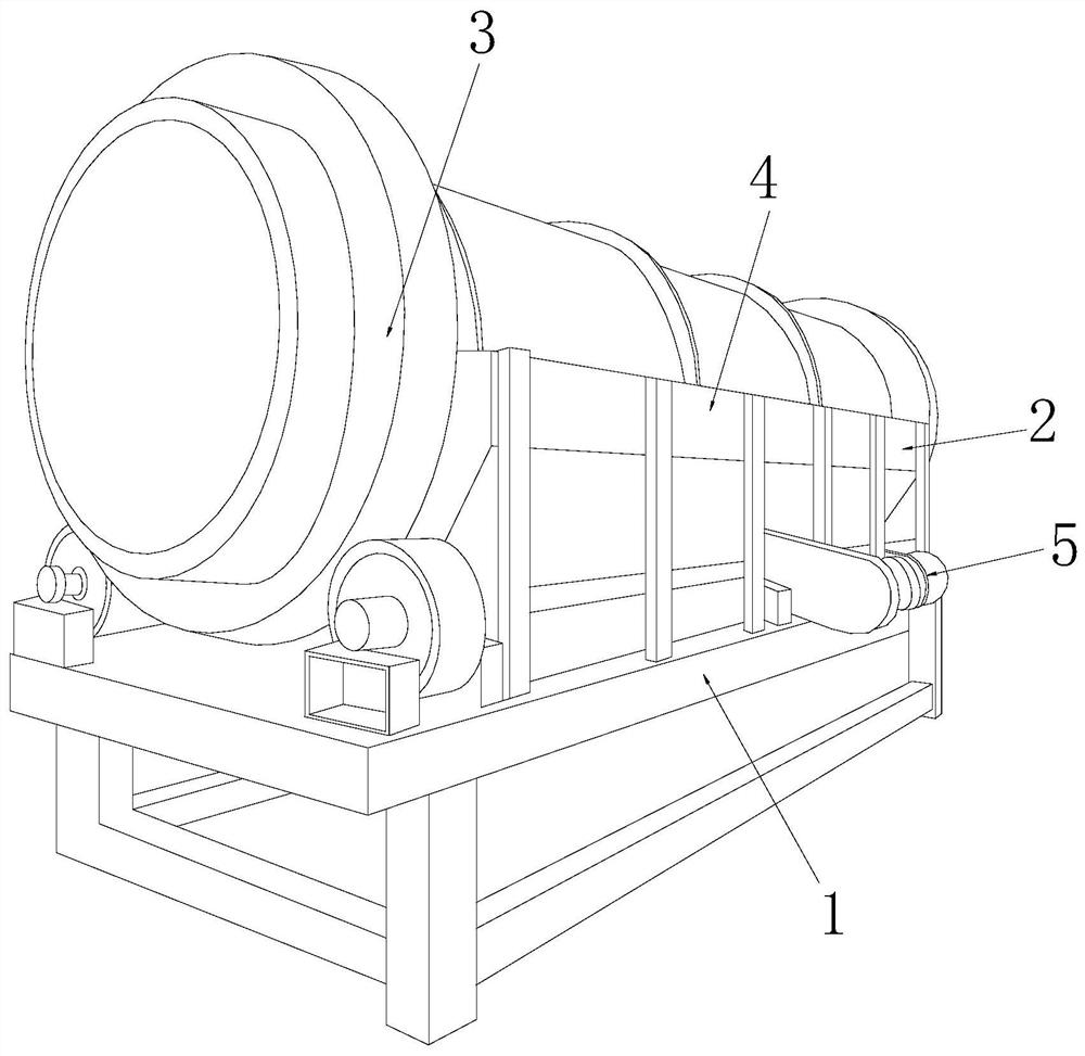
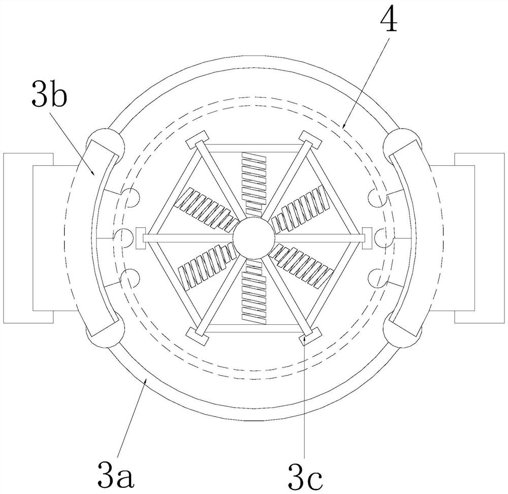
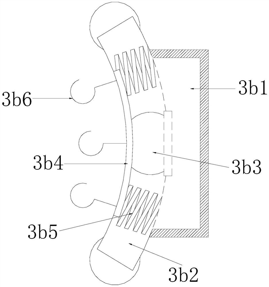
[0029] Such as Figure 1-Figure 2 As shown, a kind of construction waste screening, its structure comprises support frame 1, unloading hopper 2, loosening device 3, sieve tube 4, and described unloading hopper 2 is arranged on the upper surface of support frame 1 and is connected by electric welding, and described sieve The cylinder 4 is arranged above the discharge hopper 2 and connected by electric welding. The front end of the loosening device 3 extends into the inside of the screen cylinder 4 and is connected by electric welding. The loosening device 3 includes a sleeve frame 3a, a rolling mechanism 3b, a There are two sieve structures 3c, two of which are symmetrically installed on the left and right sides of the sleeve frame 3a and on the left and right sides of the outer side of the screen cylinder 4, and the stroked mechanism 3b pass...
no. 2 example
[0039] Such as figure 1 , figure 2 , Figure 5 , Figure 6 As shown, the present invention provides a kind of technical scheme of construction waste screening:
[0040] Such as Figure 1-Figure 2 As shown, a kind of construction waste screening, its structure comprises support frame 1, unloading hopper 2, loosening device 3, sieve tube 4, and described unloading hopper 2 is arranged on the upper surface of support frame 1 and is connected by electric welding, and described sieve The cylinder 4 is arranged above the discharge hopper 2 and connected by electric welding. The front end of the loosening device 3 extends into the inside of the screen cylinder 4 and is connected by electric welding. The loosening device 3 includes a sleeve frame 3a, a rolling mechanism 3b, a There are two sieve structures 3c, two of which are symmetrically installed on the left and right sides of the sleeve frame 3a and on the left and right sides of the outer side of the screen cylinder 4, and...
PUM
 Abstract
Description
Claims
Application Information
 - R&D Engineer
- R&D Manager
- IP Professional
- Industry Leading Data Capabilities
- Powerful AI technology
- Patent DNA Extraction
Browse by: Latest US Patents, China's latest patents, Technical Efficacy Thesaurus, Application Domain, Technology Topic, Popular Technical Reports.
© 2024 PatSnap. All rights reserved.Legal|Privacy policy|Modern Slavery Act Transparency Statement|Sitemap|About US| Contact US: help@patsnap.com