
Clutch unit with torsional vibration damper as a clutch support, and hybrid module comprising clutch unit

A technology of torsional vibration damper and clutch, which is applied in the direction of mutually meshing clutches, clutches, mechanically driven clutches, etc., can solve the problems of high cost, large structural space, high loss, etc., and achieve cost reduction and axial saving Structural space, effect of structural space reduction

Inactive Publication Date: 2020-09-01
SCHAEFFLER TECH AG & CO KG
View PDF7 Cites 0 Cited by
  • Summary
  • Abstract
  • Description
  • Claims
  • Application Information

AI Technical Summary

Problems solved by technology

[0004] However, the prior art always has the disadvantage that such a clutch unit and the upstream torsional vibration damper require a large installation space and that the costs for reducing the unevenness of rotation are very high
The prior art also has the disadvantage that in wet-running, friction-based release clutches, additionally, high losses are caused by the belt displacement; in dry-running, friction-based release clutches, the installation space requirement is large; and in a form-lock based release clutch, moreover difficult to achieve steerability

Method used


Image

  • Clutch unit with torsional vibration damper as a clutch support, and hybrid module comprising clutch unit
  • Clutch unit with torsional vibration damper as a clutch support, and hybrid module comprising clutch unit
  • Clutch unit with torsional vibration damper as a clutch support, and hybrid module comprising clutch unit

Examples


Embodiment Construction

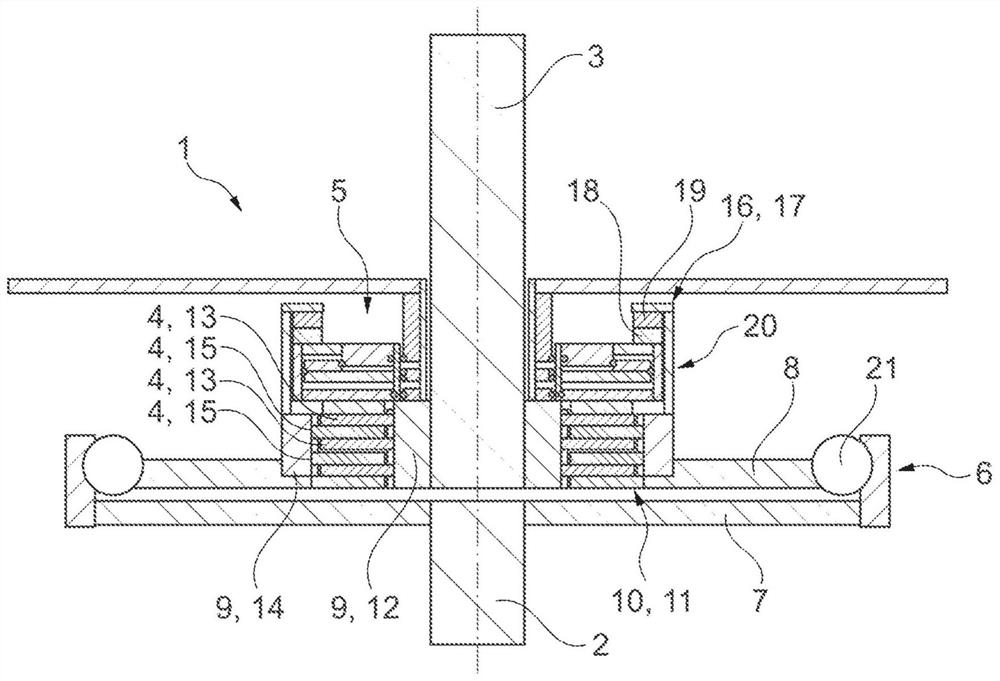
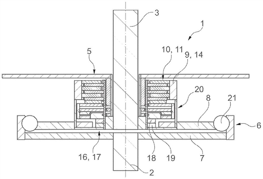
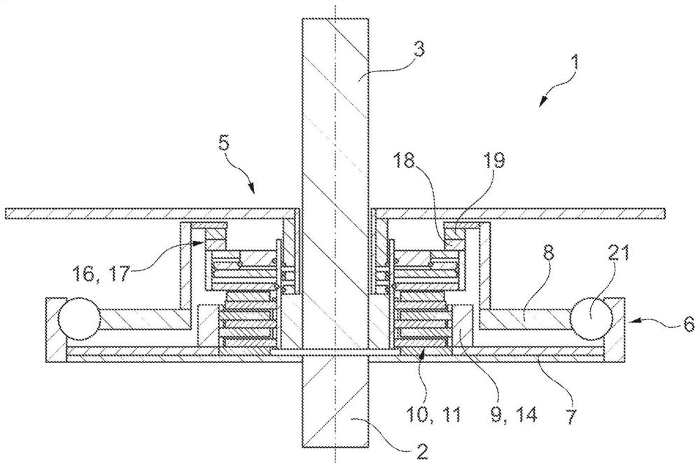
[0047] figure 1 A clutch unit 1 for a powertrain of a motor vehicle is shown. The clutch unit 1 has a torque input member 2 functioning as a driving element (or driven element) and a torque output member 3 functioning as a driven element (or driving element). The torque output member 3 can be connected in a torque-transmitting manner to the torque input member 2 via a switchable clutch / release clutch 5 using a friction pair 4 . The clutch unit 1 also has a torsional vibration damper 6 for reducing rotational irregularities, which is designed as a dual-mass flywheel. The torsional vibration damper 6 has a primary mass 7 connected to the torque input member 2 and a secondary mass 8 connected to the torque output member 3 via a clutch 5 . Primary mass 7 is damped relative to secondary mass 8 . The primary mass 7 or the secondary mass 8 simultaneously serves as a carrier 9 for the friction partners 4 of the clutch 5 or is formed in one piece with the carrier 9 .

[0048] The c...


PUM


Abstract

The invention relates to a clutch unit (1) for the power train of a motor vehicle, comprising a torque input component (2) which acts as a drive element and a torque output component (3) which acts asan output element and which can be connected to the torque input component (2) so as to transmit a torque via a clutch (5) that can be shifted using friction partners (4). The clutch (5) has two sub-clutches (10, 16), by means of which the torque input component (2) and the torque output component (3) can be connected so as to transmit a torque. One of the two sub-clutches (10, 16) is designed asa positive clutch (16, 17) and the other sub-clutch of the two sub-clutches (10, 16) is designed as a friction clutch (10, 11). The invention additionally relates to a hybrid module comprising a first drive machine, the output shaft of which can be connected to the output shaft of a second drive machine or a transmission input shaft via such a clutch unit (1).

Description

technical field [0001] The invention relates to a clutch unit for a powertrain of a motor vehicle, which has a torque input member acting as a drive element, such as a crankshaft or a component fixed relative to the crankshaft, the torque input member being used in particular for introducing a first drive Torque of a machine, such as an internal combustion engine in particular; and a torque output member acting as a driven element, such as a transmission input shaft or a driven shaft of a second drive machine, especially an electric motor, wherein the torque output member can be passed through Preferably, using a friction pair, such as friction linings and / or laminations, a shiftable clutch, in particular via a separating clutch, is connected in a torque-transmitting manner to the torque input component, wherein the clutch has two partial clutches, the torque The input member and the torque output member can be connected in a torque-transmitting manner by means of a partial cl...

Claims


Application Information

Patent Timeline
Patent Type & Authority Applications(China)
IPC IPC(8): F16D11/00B60K6/387B60K6/40F16D21/00
CPCB60K6/387F16D11/00F16D21/00F16D2011/006B60K6/20B60K17/02B60Y2200/92F16D2300/00F16D2300/22F16F15/145
Inventor 马尔科·格雷特尔洛亚尔·格奥尔格·麦克米利安马库斯·贝尔卡斯滕·迈尔
Owner SCHAEFFLER TECH AG & CO KG
Learn More