
High-concentration degradation-resistant chemical wastewater treatment equipment

A technology for chemical wastewater and treatment equipment, which is applied in water/sewage treatment equipment, electrochemical water/sewage treatment, water/sewage treatment, etc. It can solve the problems of single structure, flat and single end, low efficiency, etc., and achieve improved degradation effect, easy handling of the wire, and the effect of improving the firm performance

Inactive Publication Date: 2020-09-01
ANQING FENGYUAN CHEM
View PDF10 Cites 0 Cited by
  • Summary
  • Abstract
  • Description
  • Claims
  • Application Information

AI Technical Summary

Problems solved by technology

[0004] The purpose of the present invention is to provide a kind of high-concentration refractory chemical wastewater treatment equipment, to solve the problem that the existing wastewater treatment device proposed in the above background technology can only simply carry out wastewater treatment due to the single internal structure and process structure, resulting in time-consuming waste water treatment. There are a series of problems such as low efficiency, unsatisfactory treatment effect, low treatment accuracy, etc., and when it is processed, because its end is flat and single, it is impossible to arrange auxiliary equipment for wastewater treatment on its outside, such as water pumps. poor performance problem

Method used


Image

  • High-concentration degradation-resistant chemical wastewater treatment equipment
  • High-concentration degradation-resistant chemical wastewater treatment equipment
  • High-concentration degradation-resistant chemical wastewater treatment equipment

Examples


Embodiment Construction

[0027] The following will clearly and completely describe the technical solutions in the embodiments of the present invention with reference to the accompanying drawings in the embodiments of the present invention. Obviously, the described embodiments are only some, not all, embodiments of the present invention.

[0028] In the description of the present invention, unless otherwise stated, the meaning of "plurality" is two or more; the terms "upper", "lower", "left", "right", "inner", "outer" , "front end", "rear end", "head", "tail", etc. indicate the orientation or positional relationship based on the orientation or positional relationship shown in the drawings, and are only for the convenience of describing the present invention and simplifying the description, rather than Nothing indicating or implying that a referenced device or element must have a particular orientation, be constructed, and operate in a particular orientation should therefore not be construed as limiting ...


PUM


Abstract

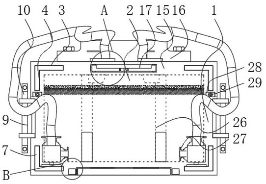
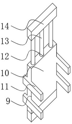
The invention relates to high-concentration degradation-resistant chemical wastewater treatment equipment. The device comprises a body and an external loading mechanism, a machine chamber is formed inthe machine body; four carrying grooves are symmetrically formed in the peripheral wall of the front end of the machine body; cushion connecting mechanisms are installed at the inner ends of the carrying grooves, the outer carrying mechanisms are arranged on the two end sides of the machine body, an upper cover is installed at the upper end of the machine body, a control box is arranged at the top end of the upper cover, embedded pieces are installed at the front end and the rear end of the upper cover, ends are arranged at the side ends of the embedded pieces, and foot mechanisms are installed at the bottom end of the machine body. The beneficial effects of the invention are that: the method is suitable for large-scale production; the invention discloses high-concentration degradation-resistant chemical wastewater treatment equipment. The distance between the upper pad and the outer piece can be adjusted through mutual movement of the upper pad and the outer piece, at the moment, theuse range of the device can be changed, the device can be flexibly adjusted conveniently, after the device is extended, a larger shielding range can be formed at the front end of the device body, a water pump at the bottom of the device body in the prior art is better shielded, and a better protection effect is achieved.

Description

technical field [0001] The invention relates to the technical field of waste water treatment, in particular to high-concentration refractory chemical waste water treatment equipment. Background technique [0002] Wastewater treatment is the use of physical, chemical and biological methods to treat wastewater, purify wastewater, reduce pollution, and achieve wastewater recycling, reuse, and make full use of water resources. Wastewater treatment devices are generally used for treatment, among which Wastewater treatment equipment is required for the treatment of some high-concentration refractory chemical wastewater. [0003] Due to the single internal structure and process structure of the existing wastewater treatment device, it can only simply treat wastewater, resulting in a series of problems such as low efficiency, unsatisfactory treatment effect, and low treatment accuracy. Because the end is flat and single, auxiliary equipment for wastewater treatment, such as water p...

Claims


Application Information

Patent Timeline
Patent Type & Authority Applications(China)
IPC IPC(8): C02F9/06
CPCC02F1/46C02F1/001C02F2201/002
Inventor 江同生
Owner ANQING FENGYUAN CHEM
Learn More