
Linear frequency modulation radar antenna pattern measuring system and method based on unmanned aerial vehicle

A technology for radar antennas and drones, applied in radio wave measurement systems, antenna radiation patterns, instruments, etc., can solve problems such as limited load capacity, inability to carry, heavy transponders, etc., achieve stable performance, reduce manpower, and cost low effect

Pending Publication Date: 2020-08-28
WUHAN UNIV +1
View PDF9 Cites 1 Cited by
  • Summary
  • Abstract
  • Description
  • Claims
  • Application Information

AI Technical Summary

Problems solved by technology

However, ordinary small UAVs have limited load capacity and cannot carry heavy transponders; large UAVs are not only expensive, but also flight licenses, areas, altitudes, etc. are strictly controlled by civil aviation authorities

Method used


Image

  • Linear frequency modulation radar antenna pattern measuring system and method based on unmanned aerial vehicle
  • Linear frequency modulation radar antenna pattern measuring system and method based on unmanned aerial vehicle
  • Linear frequency modulation radar antenna pattern measuring system and method based on unmanned aerial vehicle

Examples


Embodiment Construction

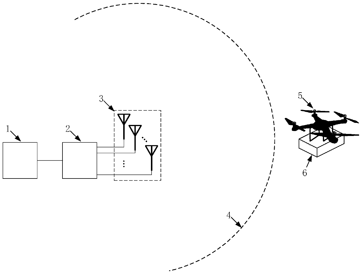
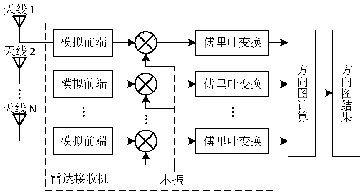
[0025] figure 1 A block diagram of an antenna pattern measurement system provided for an embodiment of the present disclosure. Such as figure 1 , the antenna pattern measurement system includes a pattern calculation subsystem 1 , a radar receiving subsystem 2 , and a UAV carrier subsystem 6 . The drone carrier system 6 includes a signal source and a coordinate / track recorder. The signal source is used to generate a single frequency and stable amplitude signal corresponding to the working frequency band of the radar antenna 3 . The radar receiving subsystem 2 is used to receive the signal transmitted by the signal source, and calculate the amplitude and phase response of signals received by different antenna channels through frequency mixing and Fourier transform. The pattern calculation subsystem 1 obtains the amplitude and phase responses of the signals received by the different antenna channels, and the flight trajectory information of the UAV obtained by the coordinate / t...


PUM


Abstract

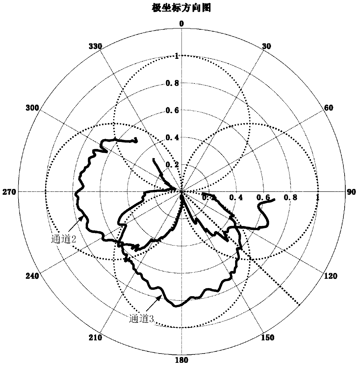
The invention discloses a linear frequency modulation radar antenna pattern measuring system and method based on an unmanned aerial vehicle. The method comprises the steps that: a signal source on theunmanned aerial vehicle generates a single-frequency and stable-amplitude signal corresponding to an antenna working frequency band; a coordinate / track recorder on the unmanned aerial vehicle acquires and stores flight track information of the unmanned aerial vehicle; the radar receiver receives signals transmitted by the signal source and calculates the amplitude and phase response of the signals received by different antenna channels; a computer acquires the amplitude and phase response of the signals received by the different antenna channels, and the flight path information of the unmanned aerial vehicle obtained by using a coordinate / path recorder, the path information is obtained to obtain the orientations of the unmanned aerial vehicle relative to a radar antenna at different moments, and further mapping is carried out to obtain antenna amplitude phase responses of different orientations, namely an antenna pattern result. The radar antenna pattern measuring device is suitable for measuring radar antenna pattern of different frequency bands, simple in structure, light, low in cost and capable of effectively overcoming limitation brought by the terrain environment around theantenna.

Description

technical field [0001] The present disclosure relates to an unmanned aerial vehicle-based chirp radar antenna pattern measurement system and method. Background technique [0002] Azimuth estimation is a key step in radar target detection, and its accuracy is affected by the characteristics of the antenna pattern. In practical applications, due to the influence of electromagnetic coupling in the surrounding environment of the antenna, the antenna pattern is easy to deviate from the ideal situation and become distorted, which will lead to a decrease in the accuracy of the orientation estimation. Accurate measurement of the actual pattern of the antenna can effectively compensate for the effects of distortion. [0003] Chirp waveform is a relatively common form of radar system, and it is widely used in different frequency bands. For chirp radar antenna pattern measurements, the traditional method is to use a transponder to move around the antenna to achieve the measurement. ...

Claims


Application Information

Patent Timeline
Patent Type & Authority Applications(China)
IPC IPC(8): G01R29/10G01S7/40
CPCG01R29/10G01S7/4004
Inventor 田应伟文必洋
Owner WUHAN UNIV
Learn More