
Wind tunnel test equipment for wind-induced particulate matter drifting

A wind tunnel test and particulate matter technology, used in aerodynamic tests, machine/structural component testing, measuring devices, etc., can solve the problems of high blocking ratio, large volume, labor and material resources, etc., and achieve a small impact on wind profile, The effect of small windward surface and low cost

Pending Publication Date: 2020-08-28
CABR TECH CO LTD
View PDF2 Cites 3 Cited by
  • Summary
  • Abstract
  • Description
  • Claims
  • Application Information

AI Technical Summary

Problems solved by technology

[0007] First, the volume of the box and the supporting structure is large, resulting in a high blocking ratio, reducing the efficiency of the wind tunnel, forcing the scale ratio of the test model to be enlarged, and reducing the accuracy of the test results;
[0008] Second, it is inconvenient to fill and replenish the vibrating screen;
[0009] Third, after the test is completed, if other types of wind tunnel tests are to be carried out in the wind tunnel, the test device must be completely dismantled, and manpower and material resources will be required to reinstall the equipment before the next snow load test

Method used


Image

  • Wind tunnel test equipment for wind-induced particulate matter drifting
  • Wind tunnel test equipment for wind-induced particulate matter drifting
  • Wind tunnel test equipment for wind-induced particulate matter drifting

Examples


Embodiment Construction

[0032] Exemplary embodiments of the present disclosure are described below with reference to the accompanying drawings. It should be understood that these specific descriptions are only used to teach those skilled in the art how to implement the present disclosure, but are not intended to exhaust all possible ways of the present disclosure, nor are they used to limit the scope of the present disclosure.

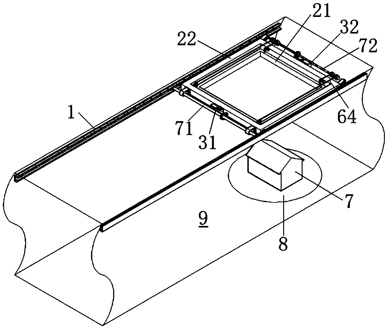
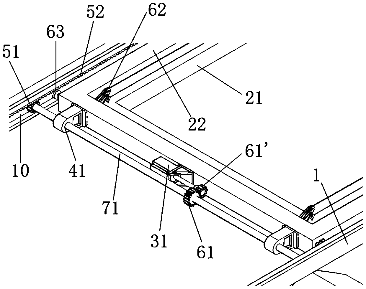
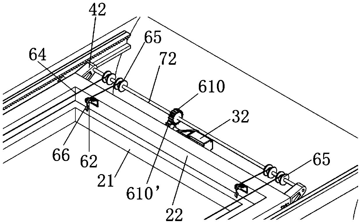
[0033] Such as Figure 1 to Figure 3 As shown, the present disclosure provides a wind tunnel test device for wind-induced particle drift (hereinafter referred to as "wind tunnel test device"), which includes a screen assembly, a drive assembly, a lifting assembly and a track 1 . The wind tunnel test equipment can be used in conjunction with the target building 7 and the turntable 8 , the turntable 8 can rotate 360 ​​degrees, and the target building 7 is arranged on the turntable 8 and can rotate together with the turntable 8 .

[0034] The wind tunnel test section includes a...


PUM


Abstract

The invention provides wind tunnel test equipment for wind-induced particulate matter drifting. The equipment is installed at a test section of a wind tunnel. The equipment comprises a driving assembly and a screen assembly, the screen assembly comprises an inner frame used for installing a screen. The screen is used for loading particulate matters, the driving assembly comprises a first motor, the driving assembly outputs rotation output by the first motor, the wind tunnel test equipment further comprises a track, the track is used for being installed on the wall of a wind tunnel, the first motor is installed on the screen assembly, the screen assembly is movably supported on the track, and the output end of the driving assembly is meshed with the track so as to drive the screen assemblyto move along the track. The equipment utilizes a flow field of a wind tunnel test section, the track is installed on the wall of the wind tunnel test section, a complex supporting structure special for supporting the track is omitted, and therefore the wind tunnel test equipment is simple in structure, small in windward side, low in cost, high in feasibility, low in blocking rate, small in wind profile influence and capable of effectively conducting snow load simulation on an actual large-span complex structure.

Description

technical field [0001] The present disclosure relates to wind tunnel test equipment, in particular to a wind tunnel test equipment for wind-induced particle drift. Background technique [0002] Conventional wind tunnel scale test is the mainstream research method of snow load in architectural design, which has the advantages of low cost and high reference. The building structure and its surrounding disturbances are reduced in a certain proportion and placed on the test bench of the wind tunnel test section. According to the similarity criterion of fluid mechanics, particles with specific diameters and densities (such as plastic chips, silica sand, baking soda, wood chips, etc.) are selected. , and a specific wind speed, the entire process of snowfall and wind-induced snow drift can be reproduced to a greater extent, and the final distribution can be used as a reference value for the snow distribution of building area. [0003] However, the existing conventional wind tunnel ...

Claims


Application Information

Patent Timeline
Patent Type & Authority Applications(China)
IPC IPC(8): G01M9/00G01M9/02G01M9/04
CPCG01M9/00G01M9/02G01M9/04
Inventor 薛原李宏海陈凯唐意
Owner CABR TECH CO LTD
Learn More