Installation structure of oil filter screen and installation method thereof
An installation structure and technology of oil filter screen, which is applied in the field of oil filter screen, can solve the problems of poor stability of oil filter screen plate, inconvenient disassembly and assembly of oil filter screen plate, rust, etc., and achieve the effect of convenient installation
- Summary
- Abstract
- Description
- Claims
- Application Information
AI Technical Summary
Problems solved by technology
Method used
Image
Examples
Embodiment 1
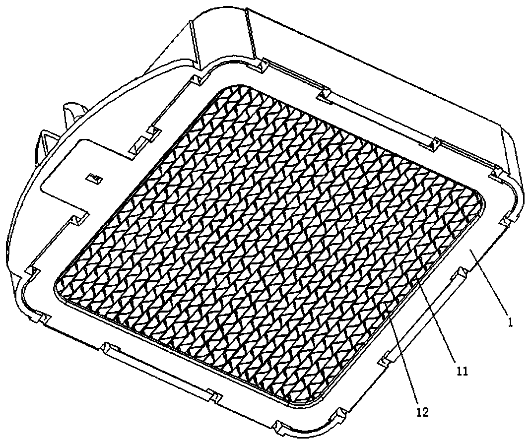
[0048] like figure 1 As shown, the oil filter body 1 includes: several partitions 11 equidistantly fixed inside the oil filter body 1 , and several filter plates equidistantly arranged inside the oil filter body 1 12. The filter plate 12 is wave-shaped, and the filter plate 12 and the partition plate 11 are distributed at intervals. Both sides of the filter plate 12 are coated with a superhydrophobic-superoleophilic layer.
[0049] The oil filter body 1 is detachably installed on the range hood body through the installation structure, so the range hood body is provided with a placement groove for installing the oil filter body 1 .
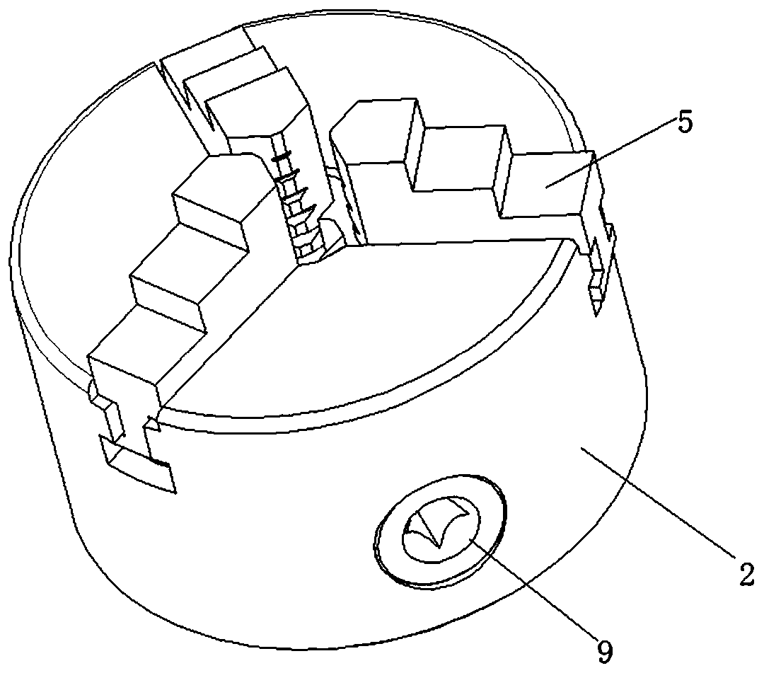
[0050]The installation structure specifically includes: connecting seat 2, connecting cylinder 3, chute 4, clamping block 5, card slot 6, support 7, rotating disc 8, rotating column 9, locking assembly 10, partition 11, Filter plate 12, conical gear ring 801, threaded ring 802, rotating rod 901, rotating torsion 902, bevel gear 903, convex strip ...
Embodiment 2
[0058] In the first embodiment above, it is pointed out that the clamping slot 6 of the clamping block 5 and the clamping column of the connecting column are clamped to realize mutual fixing. However, because the connecting cylinder itself has a length and the center of the connecting seat 2 is a hollow structure, it is difficult to ensure that the clamping column on the connecting cylinder can be accurately snapped into the corresponding slot 6, and misalignment will occur.
[0059] Therefore, the inventor made a further improvement to the connecting seat 2 based on the first embodiment: the center of the connecting seat 2 is set as a sealing structure, that is, the length of the chute 4 does not extend to the center of the connecting seat 2 . And in order to ensure that the clamping column on the connecting cylinder can be clamped into the clamping groove 6, the inner wall of the clamping block 5 is an inwardly protruding trapezoid, and the clamping groove 6 is arranged on th...
Embodiment 3
[0062] Based on Embodiment 1 and Embodiment 2, a detachable and reusable installation structure is realized, but because it is used on a range hood. The range hood will more or less vibrate when it is working. If it is not restricted, the rotating column 9 will rotate by itself when vibrating. After a long time, the connecting column and the clamping block 5 will be separated.
[0063] Therefore, the inventor made a further improvement on this basis: a locking assembly 10 is provided between the support 7 and the rotating column 9, and the locking assembly 10 includes: The fixed ring 1001 on the side wall of 7 and corresponding to the rotating column 9, the tapered rubber ring 1002 installed in the fixed ring 1001 and close to the side of the support 7, embedded in the tapered rubber ring Several balls 1003 on the inner wall of 1002, the locking bar 1004 fixed in the inner end surface of the rotating bar 901, and the circular limiting groove 1005 provided on the outer peripher...
PUM
 Abstract
Description
Claims
Application Information
 - R&D
- Intellectual Property
- Life Sciences
- Materials
- Tech Scout
- Unparalleled Data Quality
- Higher Quality Content
- 60% Fewer Hallucinations
Browse by: Latest US Patents, China's latest patents, Technical Efficacy Thesaurus, Application Domain, Technology Topic, Popular Technical Reports.
© 2025 PatSnap. All rights reserved.Legal|Privacy policy|Modern Slavery Act Transparency Statement|Sitemap|About US| Contact US: help@patsnap.com


