Multifunctional environment-friendly ceiling and mounting method thereof
An environmentally friendly and multi-functional technology, applied in the direction of ceilings, building components, buildings, etc., can solve the problems of low maintenance efficiency, cumbersome operation, dismantling, etc., and achieve the effects of high maintenance efficiency, simple operation and high assembly efficiency.
- Summary
- Abstract
- Description
- Claims
- Application Information
AI Technical Summary
Problems solved by technology
Method used
Image
Examples
Embodiment 1
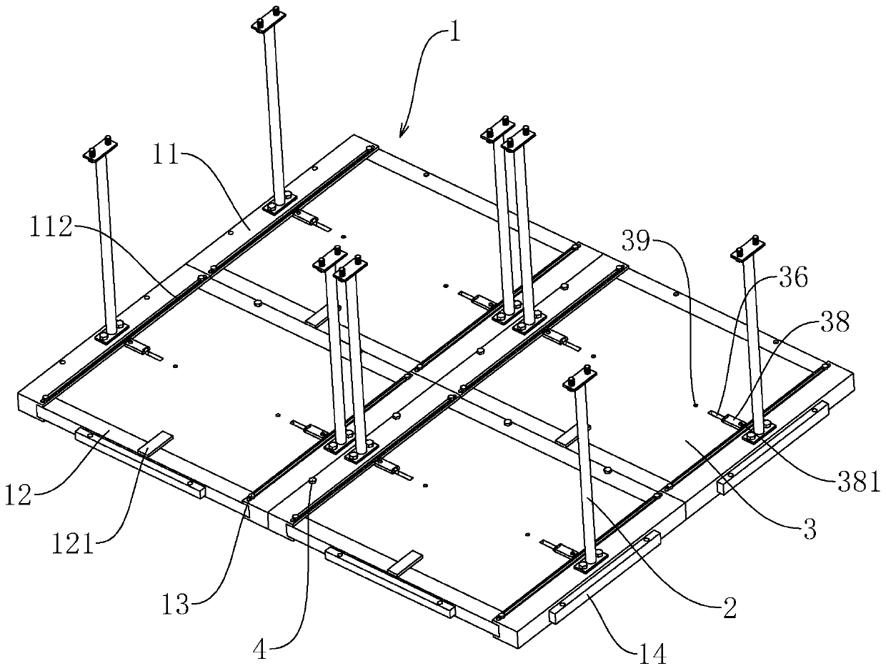
[0042] This embodiment discloses a multifunctional environment-friendly suspended ceiling, such as figure 1 , figure 2 As shown, it includes a plurality of keel frames 1 , a suspender 2 installed above the keel frames 1 , and a bottom plate 3 rotatably connected in the keel frames 1 , and two adjacent keel frames 1 are connected by connecting bolts 4 . The lower end of suspension rod 2 is connected on the keel frame 1 by fixing bolt, and the upper end of suspension rod 2 is connected on the ceiling by fixing bolt.
[0043] Such as figure 2 , image 3 As shown, each keel frame 1 includes two fixed rods 11 parallel to each other and two movable rods 12 parallel to each other. The fixed rods 11 and the movable rods 12 are perpendicular to each other and when the two are connected, the middle part is formed for the base plate 3 to extend into. hole. The opposite end faces of the two fixed rods 11 are provided with fixed grooves 111 extending along their lengthwise directions...
Embodiment 2
[0056] This embodiment discloses a method for installing a multifunctional environment-friendly suspended ceiling, which includes the following steps:
[0057] S1. Assemble the keel frame 1, move the movable rod 12 along the fixed groove 111 until the distance between the two movable rods 12 matches the width of the bottom plate 3 to be installed, and then pass the fastening bolt 13 through the waist-shaped hole 112 and connect with the movable The rod 12 is threaded to fix the movable rod 12;
[0058]S2, install the base plate 3, first drive the rotating shaft 32 into the sliding groove 31 through the push block 37, so that the insertion rod 34 stretches into the slot 35, and then turn the stopper 38 so as to be away from the first block 381 and the opening of the sliding groove 31 Engage with the first card slot 39 close to it, then extend the bottom plate 3 into the keel frame 1 and align the rotating shaft 32 with the rotating groove 113, then loosen the stop block 38 and ...
PUM
 Abstract
Description
Claims
Application Information
 - R&D
- Intellectual Property
- Life Sciences
- Materials
- Tech Scout
- Unparalleled Data Quality
- Higher Quality Content
- 60% Fewer Hallucinations
Browse by: Latest US Patents, China's latest patents, Technical Efficacy Thesaurus, Application Domain, Technology Topic, Popular Technical Reports.
© 2025 PatSnap. All rights reserved.Legal|Privacy policy|Modern Slavery Act Transparency Statement|Sitemap|About US| Contact US: help@patsnap.com


