
Moving bed biofilm reaction system

A moving bed biofilm and reaction system technology, applied in the field of sewage treatment, can solve the problems of low sewage treatment efficiency and poor quality, and achieve the effect of improving sewage treatment efficiency

Inactive Publication Date: 2020-08-28
深圳市辰中环境技术有限公司 +1
View PDF6 Cites 1 Cited by
  • Summary
  • Abstract
  • Description
  • Claims
  • Application Information

AI Technical Summary

Problems solved by technology

[0004] The purpose of the present invention is to provide a moving bed biofilm reaction system, which solves the problems of low sewage treatment efficiency and poor quality in the moving bed biofilm reaction system

Method used


Image

  • Moving bed biofilm reaction system
  • Moving bed biofilm reaction system
  • Moving bed biofilm reaction system

Examples


Embodiment Construction

[0054] The following will clearly and completely describe the technical solutions in the embodiments of the present invention with reference to the accompanying drawings in the embodiments of the present invention. Obviously, the described embodiments are only some, not all, embodiments of the present invention. Based on the embodiments of the present invention, all other embodiments obtained by persons of ordinary skill in the art without creative efforts fall within the protection scope of the present invention.

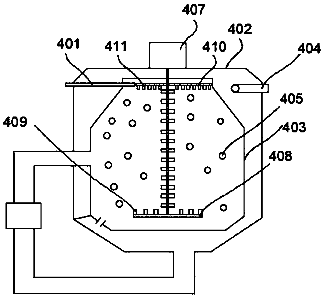
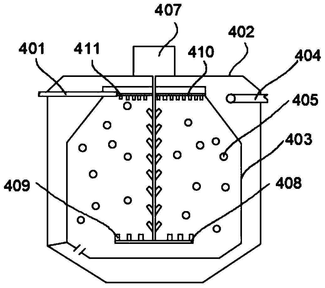
[0055] see figure 1, the present invention provides a sewage treatment system comprising: a sewage tank 100, a grid well 200, a regulating tank 300 and a moving bed biofilm reaction system 400, wherein the grid well 200 is connected to the sewage tank 100, and the regulating tank 300 is connected to the grid well 200 is connected, and the moving bed biofilm reaction system 400 is connected with the regulating tank 300 . The grid width of the grid well is, for exam...


PUM


Abstract

The invention discloses a moving bed biofilm reaction system, and belongs to the technical field of sewage treatment. The moving bed biofilm reaction system comprises: a first water inlet pipe; an anoxic reactor communicated with the first water inlet pipe; an anaerobic reactor communicated with the anoxic reactor; and the aerobic reactor is communicated with the anaerobic reactor. The system solves the problems of low sewage treatment efficiency and poor quality of a moving bed biofilm reaction system.

Description

technical field [0001] The invention belongs to the technical field of sewage treatment, in particular to a moving bed biofilm reaction system. Background technique [0002] With the rapid development of my country's industry, more and more industries will produce a large amount of high-concentration organic wastewater, such as petrochemical, printing and dyeing, papermaking, pharmaceutical, leather, cosmetics and other industries. The amount of these high-concentration organic wastewater is large and scattered. A large amount of organic pollutants and nitrogen elements contained in the sewage will undergo oxidation and decomposition reactions when discharged into the surface water body. Oxygen deficiency causes aquatic animals such as fish in the water body to be unable to breathe and die, and the dead aquatic animals undergo anaerobic decomposition in the water body and produce malodorous gases such as hydrogen sulfide and methane, and at the same time make the water body ...

Claims


Application Information

Patent Timeline
Patent Type & Authority Applications(China)
IPC IPC(8): C02F3/26C02F3/08
CPCC02F3/26C02F3/08C02F2209/22C02F1/001Y02W10/10
Inventor 陈卫军刘岩军
Owner 深圳市辰中环境技术有限公司
Learn More