
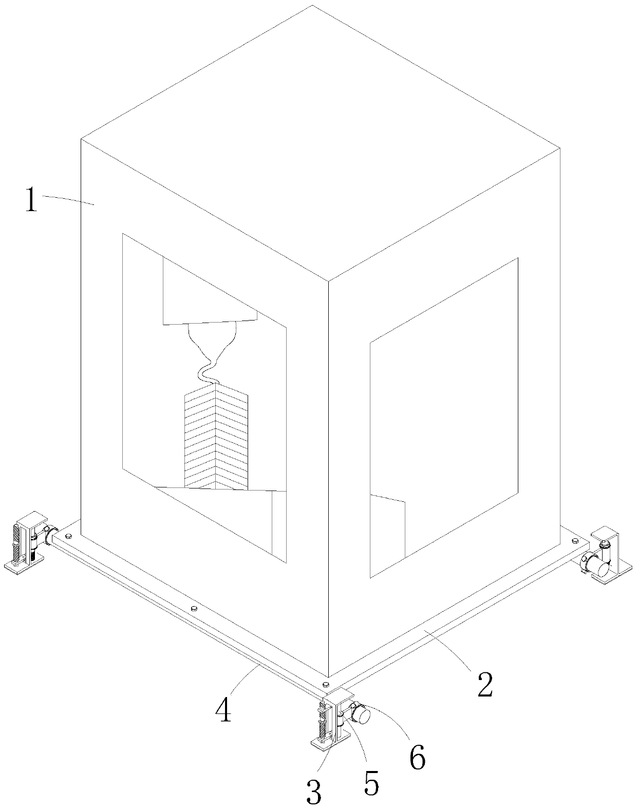
3D printing machine with data collection and storage functions

A 3D printer, storage function technology, applied in mechanical equipment, springs/shock absorbers, vibration suppression adjustment, etc., can solve the problem of inability to adjust the vibration frequency and amplitude, printing accuracy and noise reduction buffer level of 3D printers according to actual use conditions. Adaptive adjustment, vibration of the body, etc., to improve the printing effect, improve the service life, and reduce the friction

Pending Publication Date: 2020-08-28
申志杰
View PDF8 Cites 0 Cited by
  • Summary
  • Abstract
  • Description
  • Claims
  • Application Information

AI Technical Summary

Problems solved by technology

[0004] In order to make up for the deficiencies of the existing technology, solve the problem that the machine body vibrates during operation, and noise is generated inside the machine body or between it and the ground, which affects other people who are working or resting. During the printing process, the vibration frequency and frequency of the 3D printer cannot be adjusted according to the actual use range, resulting in the problem that the printing accuracy and noise reduction buffering degree cannot be adjusted adaptively. This invention proposes a 3D printer with data collection and storage functions

Method used


Image

  • 3D printing machine with data collection and storage functions
  • 3D printing machine with data collection and storage functions
  • 3D printing machine with data collection and storage functions

Examples


Embodiment approach

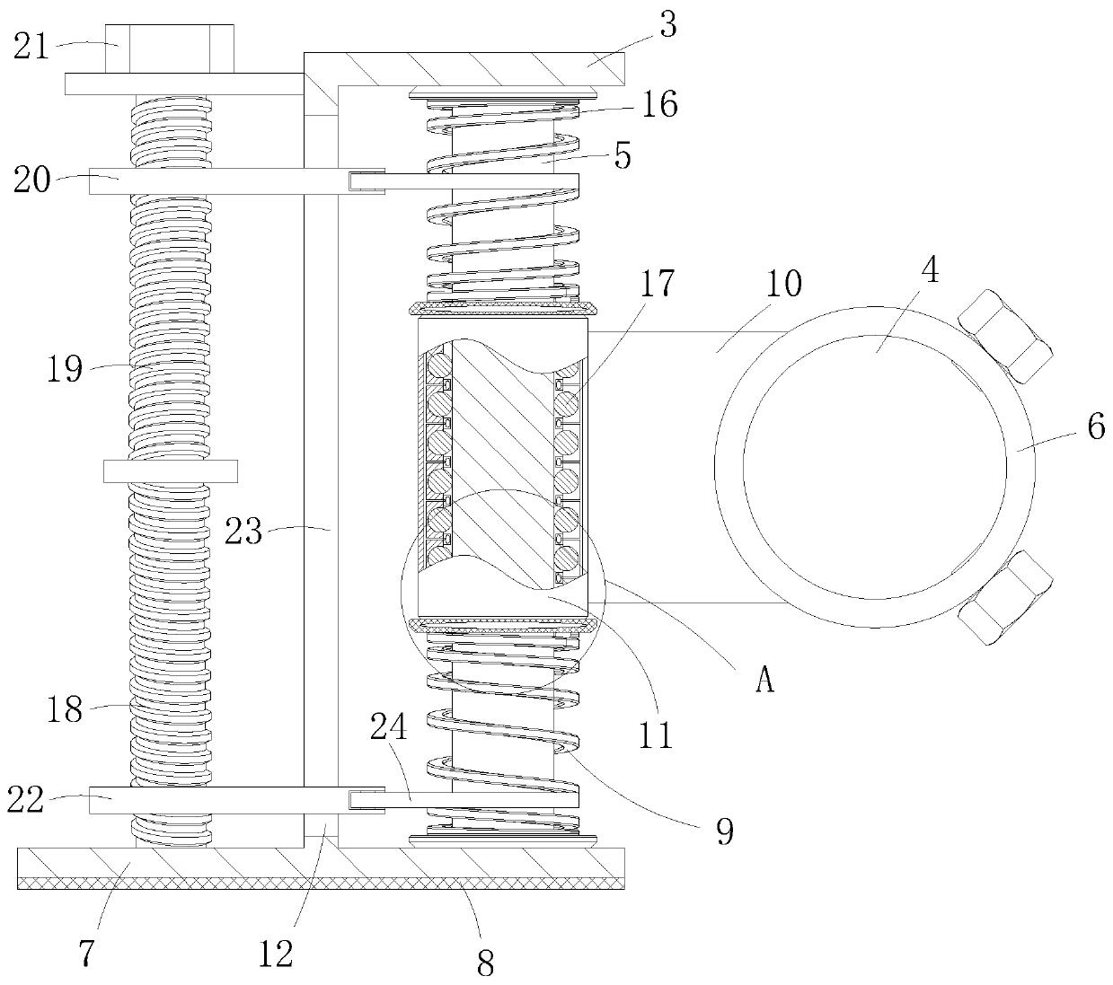
[0025] As an embodiment of the present invention, the upper surface of the flat bottom 7 of the support member 3 is rotatably connected with a first screw 18; the first screw 18 is arranged opposite to the sliding post 5; the upper end of the first screw 18 is fixedly connected There is a connecting block; the upper surface of the connecting block is fixedly connected with a second screw 19; the screw thread of the second screw 19 is opposite to that of the first screw 18; the upper end of the second screw 19 is rotatably connected with a fixed plate 20; The fixing plate 20 is fixedly connected to the surface of the L-shaped part 12 of the support member 3; the second screw rod 19 is set through the fixing plate 20, and the surface of one end of the second screw rod 19 passing through the fixing plate 20 is fixedly sleeved with a knob 21; Both the surface of the first screw 18 and the second screw 19 are threaded with a sliding plate 22; the surface of the L-shaped portion 12 o...


PUM


Abstract

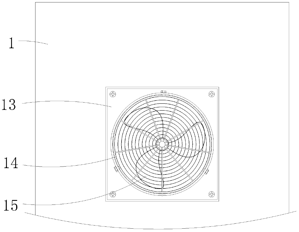
The invention belongs to the technical field of 3D printing machines, and particularly relates to a 3D printing machine with data collection and storage functions. The 3D printing machine comprises aprinting machine body, a bottom plate is fixedly connected to the bottom surface of the printing machine body, anti-knock mechanisms are arranged on the two symmetric sides of the lower surface of thebottom plate, the anti-knock mechanisms comprise connecting pipes with the two sides of the lower surface of the bottom plate being fixedly connected through bolts, sleeves are connected to the two ends of the connecting pipes through connecting pieces, the sleeves are slidably connected to sliding columns being in a vertical state, and the two ends of the sliding columns are fixedly connected into a supporting piece. Meanwhile, first springs are fixedly connected between the bottom end surfaces of the sleeves and the corresponding surface of the supporting piece, the first springs are arranged on the sliding columns in a string mode, and a heat dissipation mechanism used for performing the heat dissipation on the interior of a machine body is further arranged on the rear shell of the printing machine body. The 3D printing machine with the data collection and storage functions is suitable for office space or space with a smaller production place, and the noise pollution can be greatlyreduced through the anti-knock mechanisms, so that the purpose of being convenient for practical use is achieved.

Description

technical field [0001] The invention belongs to the technical field of 3D printers, and specifically relates to a 3D printer with data collection and storage functions. Background technique [0002] 3D printer, also known as three-dimensional printer, is a cumulative manufacturing technology, that is, a machine of rapid prototyping technology. It is based on a digital model file and uses special wax and powdered metal or plastic. Print layers of adhesive material to create three-dimensional objects. [0003] With the popularization of wireless transmission modules such as the Internet and Bluetooth, 3D printers with functions such as data collection and storage are widely used. The body will inevitably vibrate during operation, and then noise will be generated inside the body or between it and the ground. The number of reflections in a small space is more, the noise pollution caused is more serious, and it is easy to affect other people who are working or resting. The buff...

Claims


Application Information

Patent Timeline
Patent Type & Authority Applications(China)
IPC IPC(8): B29C64/20B33Y30/00F16F15/08
CPCB33Y30/00B29C64/20F16F15/085
Inventor 申志杰赵纪明
Owner 申志杰
Learn More