Metal continuous punching die

A stamping die and metal technology, which is applied in the field of metal continuous stamping dies, can solve problems such as insufficient stability of the die body, and achieve the effects of convenient discharge, protection of the stamping plate and metal, and stable stamping

Inactive Publication Date: 2020-08-28
广州百畅信息科技有限公司
View PDF10 Cites 2 Cited by
  • Summary
  • Abstract
  • Description
  • Claims
  • Application Information

AI Technical Summary

Problems solved by technology

[0004] The purpose of the present invention is to provide a metal continuous stamping die to solve the problem that the die body is not stable enough during the stamping process in the above-mentioned background technology

Method used


Image

  • Metal continuous punching die
  • Metal continuous punching die
  • Metal continuous punching die

Examples


Embodiment Construction

[0031] The following will clearly and completely describe the technical solutions in the embodiments of the present invention with reference to the accompanying drawings in the embodiments of the present invention. Obviously, the described embodiments are only some, not all, embodiments of the present invention. Based on the embodiments of the present invention, all other embodiments obtained by persons of ordinary skill in the art without making creative efforts belong to the protection scope of the present invention.

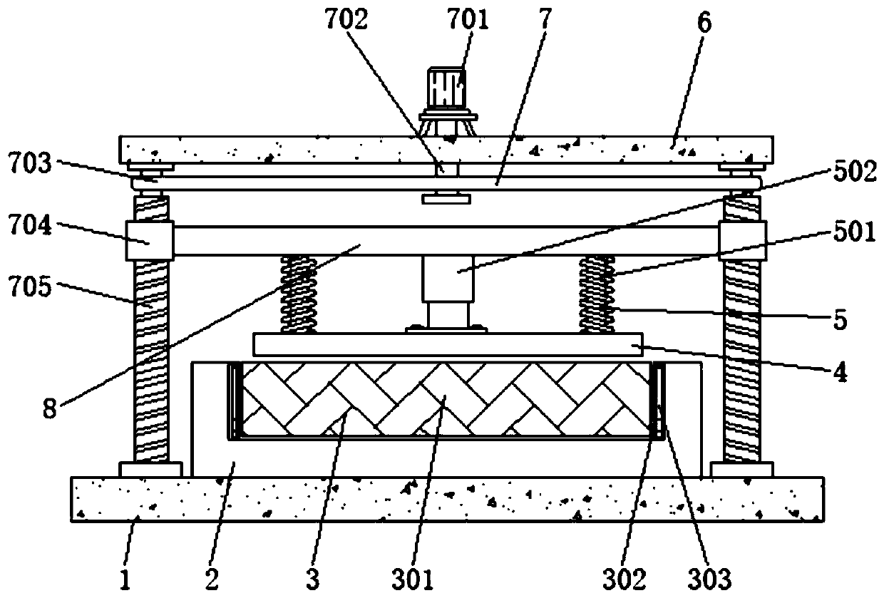
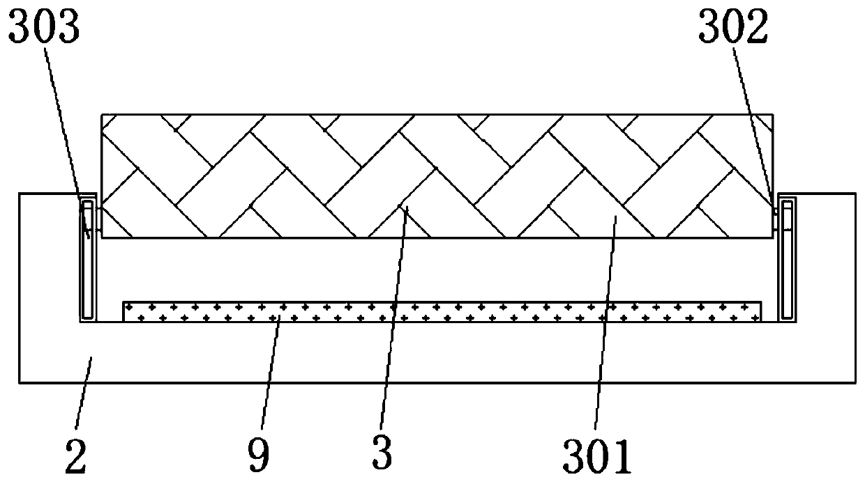
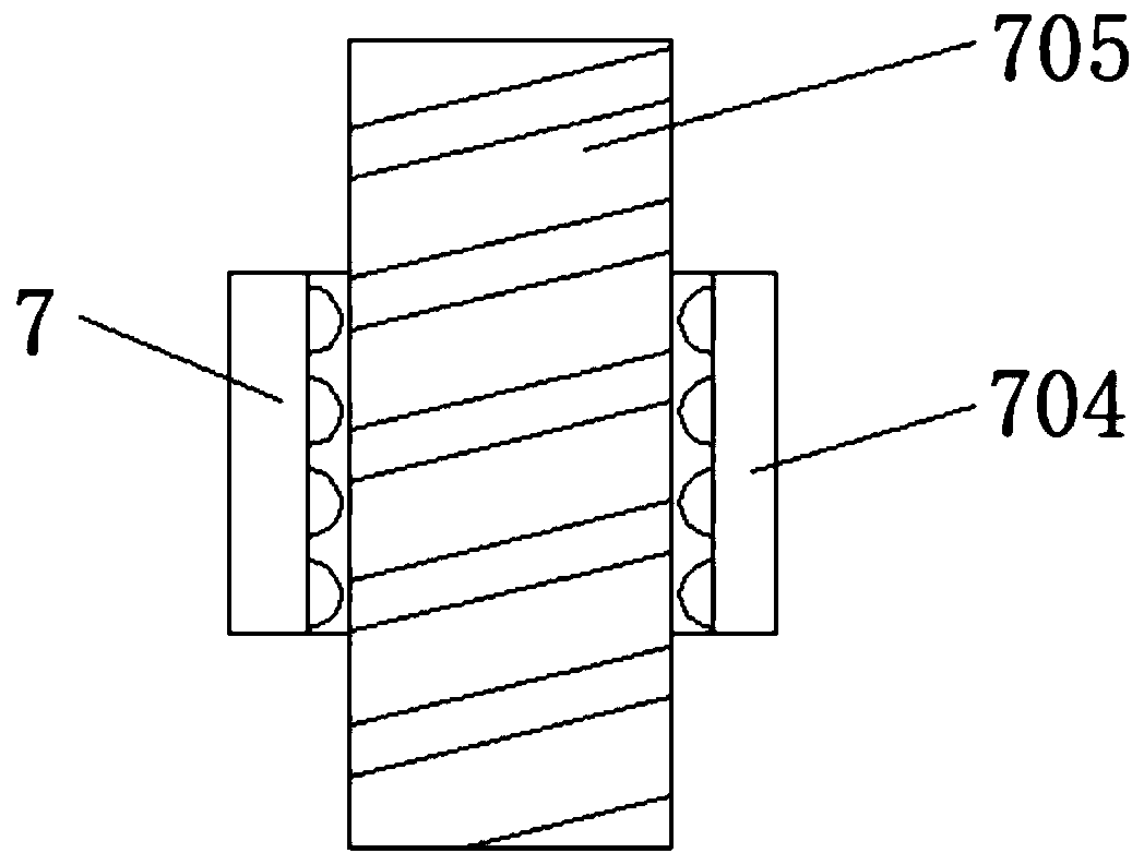
[0032] see Figure 1-4 , an embodiment provided by the present invention: a metal continuous stamping die, including a bottom plate 1, a mold body 2, a stamping plate 4 and a fixing plate 9, a mold body 2 is installed on the top of the bottom plate 1, and the two ends of the outer wall of the mold body 2 Both are equipped with a discharge structure 3, the discharge structure 3 includes a discharge plate 301, a slider 302 and a chute 303, the discharge plate 30...


PUM


Abstract

The invention discloses a metal continuous punching die. A bottom plate, a die body, a punching plate and a fixing plate are included. The die body is arranged at the top end of the bottom plate. Discharging structures are arranged at the two ends of the outer wall of the die body. The fixing plate is arranged at the bottom end in the die body. Stable structures are arranged on the two sides of the top end of the bottom plate. Connecting rods are arranged at the bottom end of the top plate. Damping structures are arranged at the bottom ends of the connecting rods. The punching plate is arranged at the bottom ends of the damping structures. Through the arrangement of the stable structures, when the die needs to be punched, an external power source is conducted at the time, a servo motor isstarted and drives a rotation rod to rotate, the rotating rotation rod makes screws rotate through a belt, drive blocks can slide on the screws up and down, and accordingly the metal punching effect is achieved; and under the action of the two screws, a more stable effect can be achieved during impacts.

Description

technical field [0001] The invention relates to the technical field of stamping dies, in particular to a metal continuous stamping die. Background technique [0002] Metal continuous stamping die is a kind of mold used for metal stamping. With the development of society and the improvement of people's living standards, some metals need to be stamped before use, so metal needs a mold for stamping, but now The kind device that has still has certain problem and defective. [0003] At present, the metal continuous stamping die does not have a stable structure for stabilizing the stamping of the die body during the stamping process, which makes the die body not stable enough during the stamping process. Contents of the invention [0004] The purpose of the present invention is to provide a metal continuous stamping die to solve the problem that the die body is not stable enough during the stamping process in the above-mentioned background technology. [0005] In order to achi...

Claims


Application Information

Patent Timeline
Patent Type & Authority Applications(China)
IPC IPC(8): B21D37/10F16F15/067B21D22/02B21D45/04H02K7/10
CPCB21D22/02B21D37/10B21D45/04F16F15/067H02K7/1008
Inventor 邹林
Owner 广州百畅信息科技有限公司
Why Eureka
Try Eureka