Eureka AIR delivers breakthrough ideas for toughest innovation challenges, trusted by R&D personnel around the world.

Hydraulic rubber pipe

A rubber hose and hydraulic technology, which is applied in the direction of hose connection devices, pipes/pipe joints/fittings, mechanical equipment, etc., can solve problems such as lengthy pipelines, delays in construction period, and inability to change lengths, so as to avoid lengthy pipelines and save high pressure Hoses and the effect of improving piping efficiency

Inactive Publication Date: 2020-08-25
陈艳艳
View PDF0 Cites 3 Cited by
  • Summary
  • Abstract
  • Description
  • Claims
  • Application Information

AI Technical Summary

Problems solved by technology

[0002] At present, in the hydraulic system, hydraulic hoses are the most used when connecting the oil circuits between various components. Since the existing hydraulic hoses are made by crimping and tightening the buckle-type hose joints and high-pressure hose connection ends, The length of the high-pressure hose cannot be changed after the production is completed. In order to avoid the length of the hydraulic system pipeline, before the hydraulic system is connected to the pipeline, the length of the pipeline needs to be measured according to the distance between the components, and the hydraulic hose manufacturer can customize the hydraulic hose according to the length. Rubber hoses will affect the assembly process of the hydraulic system during the piping process of the hydraulic system, delaying the construction period, and if there are errors in size measurement, the customized hydraulic hoses may not be used, which will cause waste; The connection between the hose and the buckle-type joint is prone to damage and leakage, so the entire rubber hose can only be discarded, which will cause a lot of waste and bring inconvenience to production and life

Method used

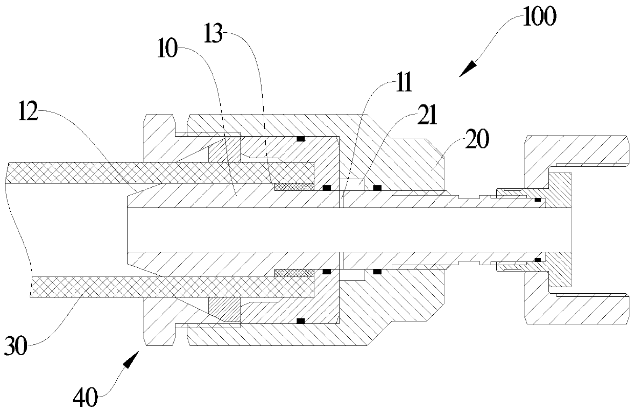

Image

  • Hydraulic rubber pipe
  • Hydraulic rubber pipe
  • Hydraulic rubber pipe

Examples


Embodiment Construction

[0018] The following will clearly and completely describe the technical solutions in the embodiments of the present invention with reference to the accompanying drawings in the embodiments of the present invention. Obviously, the described embodiments are only some, not all, embodiments of the present invention. Based on the embodiments of the present invention, all other embodiments obtained by persons of ordinary skill in the art without making creative efforts belong to the protection scope of the present invention.

[0019] It should be noted that when a component is said to be "mounted on" another component, it may be directly on the other component or there may be an intervening component. When a component is said to be "set on" another component, it may be set directly on the other component or there may be an intervening component at the same time. When a component is said to be "fixed" to another component, it may be directly fixed to the other component or there may ...


PUM


Abstract

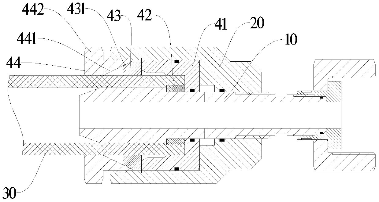
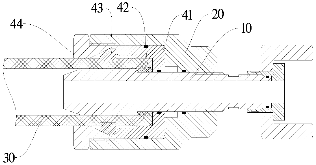
Disclosed is a hydraulic rubber pipe, comprising: a joint inner sleeve, a joint outer sleeve sleeved outside the joint inner sleeve, and a high-pressure hose disposed between the joint inner sleeve and the joint outer sleeve. The right end of the joint outer sleeve is in threaded connection to the joint inner sleeve; and a cavity is formed between the left end of the joint outer sleeve and the outer surface of the joint inner sleeve. The hydraulic rubber pipe further comprises a rubber pipe locking mechanism; and the rubber pipe locking mechanism is disposed in the cavity, and is used for locking the high-pressure hose on the joint inner sleeve. The present invention has the following advantages: a joint and the high-pressure hose are connected in a mechanical buckling manner; the customization of the hydraulic rubber pipe according to the distance of a hydraulic element can be prevented; the high-pressure hose having an appropriate length is shorn out for connection only by means of the distance of the element, so that the pipe dispensing efficiency can be improved, and the pipeline redundancy caused by wrong measurement in pipe dispensing can be prevented; and the destructed position of the high-pressure hose can be shorn off for other purposes, so that the utilization rate is greatly increased, and the cost is saved.

Description

technical field [0001] The invention belongs to the technical field of rubber hoses, in particular to a hydraulic rubber hose. Background technique [0002] At present, in the hydraulic system, hydraulic hoses are the most used when connecting the oil circuits between various components. Since the existing hydraulic hoses are made by crimping and tightening the buckle-type hose joints and high-pressure hose connection ends, The length of the high-pressure hose cannot be changed after the production is completed. In order to avoid the length of the hydraulic system pipeline, before the hydraulic system is connected to the pipeline, the length of the pipeline needs to be measured according to the distance between the components, and the hydraulic hose manufacturer can customize the hydraulic hose according to the length. Rubber hoses will affect the assembly process of the hydraulic system during the piping process of the hydraulic system, delaying the construction period, and...

Claims


Application Information

Patent Timeline
Patent Type & Authority Applications(China)
IPC IPC(8): F16L33/16F16L33/18F16L33/22
CPCF16L33/16F16L33/18F16L33/224F16L33/225
Inventor 李来滨邵建国
Owner 陈艳艳
Why Eureka
Eureka Blog
Learn More