
Bi-directional leading shoe type brake mechanism based on drum brake

A braking mechanism and leading shoe technology, applied in hydraulic drum brakes, mechanically driven drum brakes, brake parts, etc., can solve the problem of reducing the load on the brake cylinder, shortening the service life of the friction lining and increasing the friction lining Wear and other problems, to achieve the effect of increasing braking efficiency, reducing wear and prolonging service life

Inactive Publication Date: 2020-08-25
周长虹
View PDF9 Cites 2 Cited by
  • Summary
  • Abstract
  • Description
  • Claims
  • Application Information

AI Technical Summary

Problems solved by technology

[0005] The invention provides a two-way leading shoe brake mechanism based on drum brakes, which can simultaneously apply pressure to both ends of the brake shoe, reduce the bearing load of the brake pressure cylinder during work, and simultaneously apply pressure, vibration and wear Smaller advantages, it solves the problem that when the existing two-way leading shoe brake uses the brake pressure cylinder to squeeze the brake shoe, it also applies pressure on one end of the two sets of brake shoes, causing the brake pressure cylinder to work. The load pressure is relatively large, and the wear is serious under the same working environment. Moreover, due to the uneven force on both ends of the brake shoe, the vibration caused by the brake is relatively large, which greatly increases its performance. For the wear of the friction plate, the service life of the friction plate is further shortened

Method used


Image

  • Bi-directional leading shoe type brake mechanism based on drum brake
  • Bi-directional leading shoe type brake mechanism based on drum brake
  • Bi-directional leading shoe type brake mechanism based on drum brake

Examples


Embodiment Construction

[0023] The following will clearly and completely describe the technical solutions in the embodiments of the present invention with reference to the accompanying drawings in the embodiments of the present invention. Obviously, the described embodiments are only some, not all, embodiments of the present invention. Based on the embodiments of the present invention, all other embodiments obtained by persons of ordinary skill in the art without making creative efforts belong to the protection scope of the present invention.

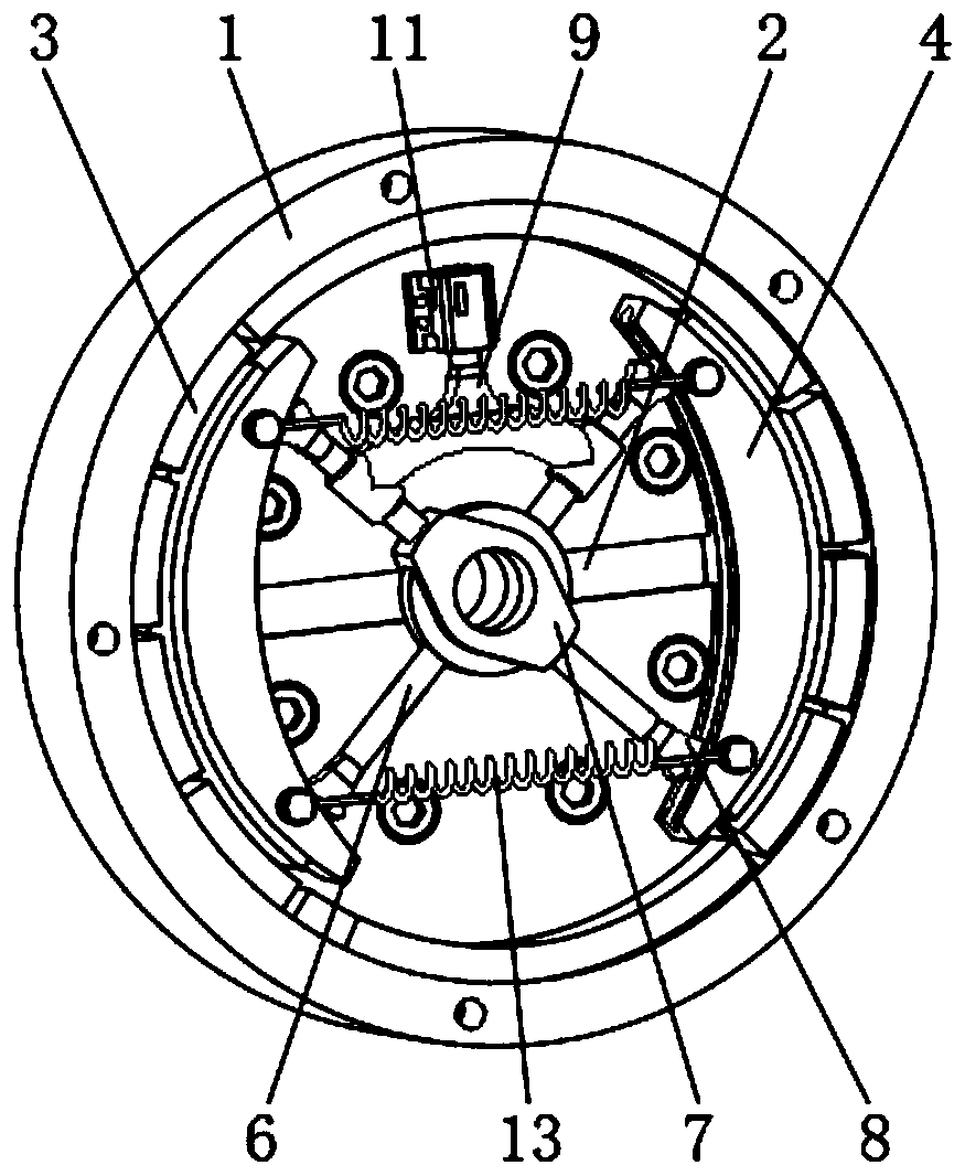
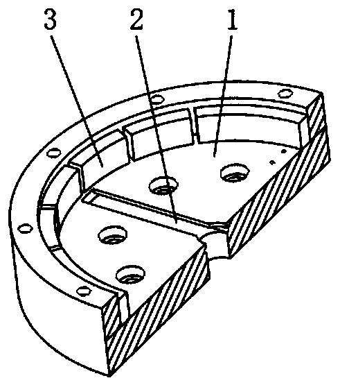
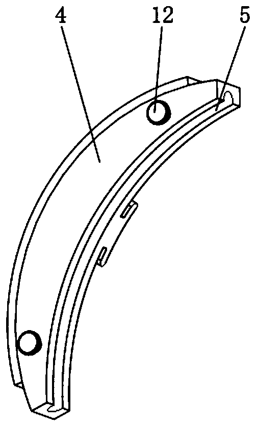
[0024] see Figure 1-5 , a two-way leading shoe brake mechanism based on drum brakes, including a brake drum 1, a sliding groove 2 is provided in the middle of the brake drum 1 surface, and a friction plate 3 is provided on the inner wall of the brake drum 1, The sliding groove 2 on the brake drum 1 is movably connected with a brake shoe 4, one side of the brake shoe 4 is provided with a spherical chute 5, and the inside of the brake drum 1 is provided with a ...


PUM


Abstract

The invention relates to the technical field of automobile brake equipment, and discloses a bi-directional leading shoe type brake mechanism based on a drum brake. The mechanism comprises a brake drum, wherein a sliding groove is formed in the middle of the surface of the brake drum, a friction plate is arranged on the inner wall of the brake drum, and a ball-shaped sliding groove is formed in oneside of a brake shoe. According to the bi-directional leading shoe type brake mechanism based on the drum brake, through arrangement of a brake connecting rod I, a brake connecting rod II and brake ball seats, and using a manner of axis rotation, the four brake ball seats fixedly mounted at both ends of the brake connecting rod I and the brake connecting rod II may move synchronously. Compared with the prior art, it can be guaranteed that the upper end and the lower end of the brake shoe are simultaneously opened outwards to apply pressure to the friction plate, so that load pressure to be borne by a dynamic pressure cylinder during braking is effectively relieved, meanwhile, stresses on the two ends of the brake shoe are uniform, vibration generated by the brake shoe during braking is effectively reduced, and abrasion to the friction plate by the brake shoe is further reduced, and the service life of the friction plate is prolonged.

Description

technical field [0001] The invention relates to the technical field of automobile brake equipment, in particular to a drum brake-based two-way leading shoe brake mechanism. Background technique [0002] The drum brake is a braking device that uses the stationary brake pads in the brake drum to rub against the inner surface of the friction drum that rotates with the rotation of the wheel to generate corresponding friction to reduce the rotation speed of the wheel and achieve the purpose of braking. , because of its good self-braking effect and large braking force, it is widely used in the rear wheel braking of small cars and the braking of large cars. [0003] Among them, the two-way leading shoe brake, as a kind of drum brake structure, can effectively avoid the one-way problem of drum brakes with other structures, that is, the braking efficiency is good when moving forward, but the braking efficiency is poor when reversing. There will be a great decline, but when the exist...

Claims


Application Information

Patent Timeline
Patent Type & Authority Applications(China)
IPC IPC(8): F16D51/14F16D51/12F16D65/10F16D65/08
CPCF16D51/12F16D51/14F16D65/0031F16D65/08F16D65/10F16D2121/02F16D2121/14
Inventor 周长虹
Owner 周长虹
Learn More