
Hydraulic support and tamping mechanism

A technology of hydraulic jacks and movable beams, applied in pillars/brackets, mining equipment, earthwork drilling and mining, etc., can solve problems affecting the normal operation of the tamping mechanism and reduce the working efficiency of the hydraulic support of the tamping mechanism, and achieve simple structure, good orientation and Supporting effect, reducing accumulation effect

Pending Publication Date: 2020-08-25
ZHENGZHOU SIWEI MECHANICAL & ELECTRICAL EQUIP MFG
View PDF2 Cites 0 Cited by
  • Summary
  • Abstract
  • Description
  • Claims
  • Application Information

AI Technical Summary

Problems solved by technology

In the working environment of the hydraulic support, coal gangue often falls on the top of the rear side of the base. During the working process of the tamping mechanism, the falling coal gangue is easy to accumulate on the swing beam, the first-level cover plate and the second-level cover plate, and then affects the entire tamping. The normal work of the mechanism reduces the working efficiency of the tamping mechanism and the entire hydraulic support

Method used


Image

  • Hydraulic support and tamping mechanism
  • Hydraulic support and tamping mechanism
  • Hydraulic support and tamping mechanism

Examples


specific Embodiment 1

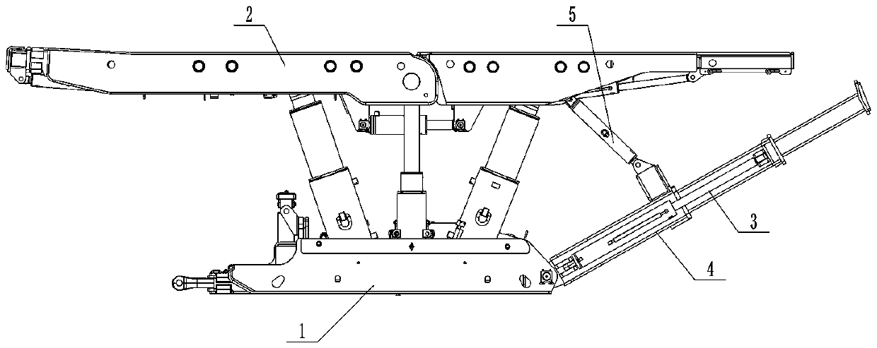
[0053] like figure 1 As shown, the hydraulic support includes a base 1, a top beam 2 is supported above the base 1, and a tamping mechanism 3 hinged on the base 1 is provided at the rear of the base 1. The tamping mechanism 3 includes a tamping beam 4, which can swing up and down. And it can also be stretched back and forth to push the material and compact the filling material within the full mining height range. In this embodiment, a swing jack 5 is hinged between the tamping beam 4 and the top beam 2 , and the tamping beam 4 can be driven to swing up and down by the swing jack 5 .

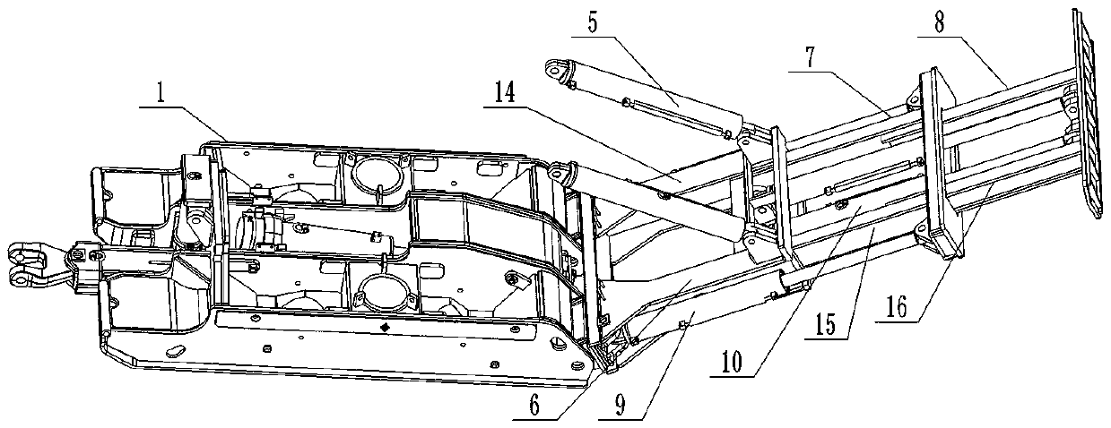
[0054] like figure 2 As shown, the tamping beam 4 includes a fixed beam section 6 and a movable beam section arranged along the length direction of the tamping beam 4, the front end of the fixed beam section 6 is hinged on the base 1, and there are two movable beam sections, which are respectively first-class movable beams Segment 7 and secondary movable beam segment 8. The first-level movabl...

specific Embodiment 2

[0066] The difference between the tamping mechanism of the hydraulic support in this embodiment and the tamping mechanism disclosed in the utility model patent document with the authorized announcement number CN201874613U is that the primary cover plate and the secondary cover plate are not set in the tamping mechanism of this embodiment, and each box The bottom plate of the body structure is a hollow structure that penetrates up and down, so that the pendulum beam, the first-level telescopic beam and the second-level telescopic beam all form a hollow structure, so that coal gangue can pass through from top to bottom and reduce accumulation in the compacting mechanism. The amount of gangue on the top improves the working efficiency of the tamping mechanism.

specific Embodiment 3

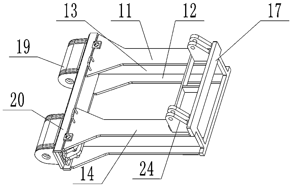
[0068] The difference from the specific embodiment 1 is that only the fixed beam section is a hollow structure formed by the frame structure, the two secondary guide columns of the first-level movable beam section are connected by connecting plates, and the two second-level guide columns of the second-level movable beam section There is also a connecting plate between the telescopic columns, and the two telescopic columns are arranged above the connecting plate between the two secondary guide columns to increase the strength of the primary movable beam section and the secondary movable beam section, and the secondary hydraulic jacks are connected Between the connecting plate and the compacting plate, and above the connecting plate of the first-level movable beam section and the connecting plate of the second-level movable beam section, so as to realize the front and rear expansion and contraction of the second-level telescopic beam section.

[0069] In other embodiments, it is ...


PUM


Abstract

The invention relates to a walking type mine top support for mining, in particular to a hydraulic support and a tamping mechanism. The tamping mechanism comprises a tamping beam capable of being extended and retracted front and back, the tamping beam comprises a fixed beam segment and at least one movable beam segment, wherein the fixed beam segment and the movable beam segments are arranged in the length direction of the tamping beam, the fixed beam segment is used for being hinged to the rear of a base, the two adjacent beam segments in the fixed beam segment and the movable beam segments are slidably assembled in a guiding mode, the two adjacent beam segments are connected through a hydraulic jack to form a telescopic beam segment, and at least one of the fixed beam segment and the movable beam segments is of a hollow structure to enable gangue to penetrate from top to bottom. According to the tamping mechanism of the hydraulic support, at least one of the fixed beam segment and themovable beam segments is of the hollow structure to enable the gangue to penetrate from top to bottom, the gangue accumulated above the tamping mechanism can be reduced, the normal work of the tamping mechanism is facilitated, and the working efficiency of the tamping mechanism and the hydraulic support can be improved.

Description

technical field [0001] The invention relates to a walking type mine roof support for mining, in particular to a hydraulic support and a compacting mechanism. Background technique [0002] Hydraulic supports are relatively important and key support equipment in mining engineering operations. With the continuous maturity of mineral mining technology, various hydraulic supports for different needs are also emerging. The commonly used filling hydraulic support includes a base, a top beam supported above the base, and a tamping mechanism hinged at the rear of the base. During the working process of the hydraulic support, the tamping mechanism can be stretched to push materials, and can also swing to tamp the gangue. The filling material is compacted within the full mining height range. [0003] The utility model patent document with the authorized announcement number CN201886413U and the authorized announcement date of June 22, 2011 discloses a tamping mechanism for gangue-fille...

Claims


Application Information

Patent Timeline
Patent Type & Authority Applications(China)
IPC IPC(8): E21D15/44E21D15/55E21D15/50
CPCE21D15/44E21D15/50E21D15/55
Inventor 崔永亮史磊王富王易玮张俊邢燕兵王梓科蒋留杰郑永强张强
Owner ZHENGZHOU SIWEI MECHANICAL & ELECTRICAL EQUIP MFG
Learn More