Tramcar contact line suspension device

A technology for trams and suspension devices, which is applied to overhead lines and other directions, can solve the problems of disconnection, large space occupation, and influence of power supply of trams, and achieve the effect of improving stability.

Active Publication Date: 2020-08-25
石家庄京铁供电器材有限公司
View PDF8 Cites 1 Cited by
  • Summary
  • Abstract
  • Description
  • Claims
  • Application Information

AI Technical Summary

Problems solved by technology

[0004] In the above-mentioned prior art solution, it solves the problem that the existing contact wire suspension device has a complex structure and takes up a large space
However, during the operation of the tram, there will be up and down vibrations, which will drive the contact wire to move up and down thereupon. However, in the above-mentioned scheme, the contact wire can only follow the positioning insulating tube to rotate along its hinge, so that the contact wire and The contact end of the tram has a certain angle. When the vibration amplitude is too large, the angle between the contact wire and the tram will be too large and it will be disengaged, which will affect the power supply of the tram.

Method used


Image

  • Tramcar contact line suspension device
  • Tramcar contact line suspension device
  • Tramcar contact line suspension device

Examples


Embodiment Construction

[0035] The present invention will be described in further detail below in conjunction with the accompanying drawings.

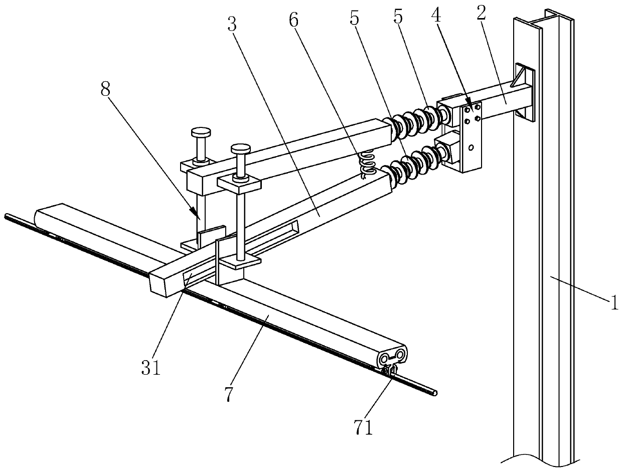
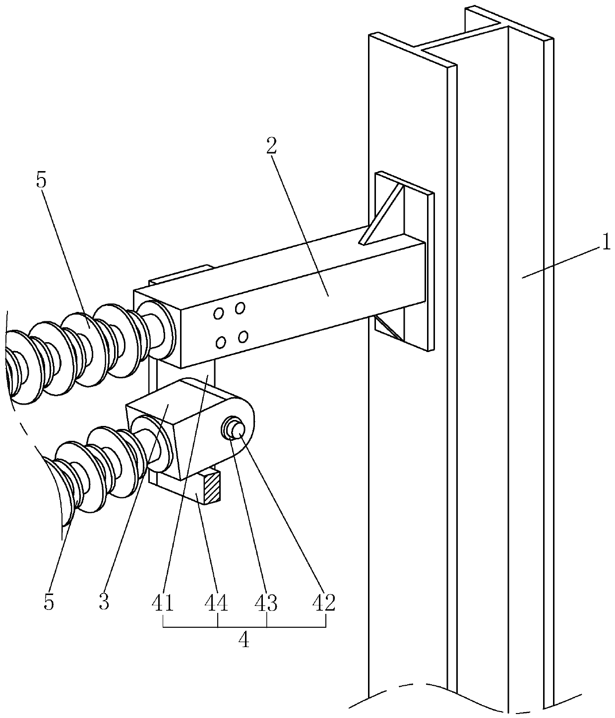
[0036] refer to figure 1 , is a trolley contact line suspension device disclosed in the present invention, comprising a column 1, the column 1 is made of I-beam, and the column 1 is located on one side of the tram track and arranged along the vertical direction. The side of the column 1 top near the track is fixed with a fixed arm 2, the fixed arm 2 is set as a hollow square tube with both ends closed, and the fixed arm 2 is arranged in the horizontal direction and extends to the top of the track.

[0037] refer to figure 1 , the lower part of the fixed arm 2 is provided with a floating arm 3, the floating arm 3 and the fixed arm 2 are located on the same vertical plane, and the end of the floating arm 3 close to the column 1 is connected to the fixed arm 2 Component 4, the floating arm 3 is hinged to the bottom of the fixed arm 2 through the connecting com...


PUM


Abstract

The invention relates to a tramcar contact line suspension device. The device comprises a stand column arranged on one side of a tramcar rail, a fixed cantilever fixedly arranged on the top surface ofthe stand column and located above the rail, a floating cantilever arranged below the fixed cantilever, a spring arranged between the floating cantilever and the fixed cantilever, and a wire clamp which is arranged at one end, away from the stand column, of the floating cantilever and used for clamping a contact line. A connecting assembly for hinging the floating cantilever and the fixed cantilever is arranged between the floating cantilever and the fixed cantilever, and a floating mechanism for enabling the wire clamp to only float in a height direction is further arranged between the wireclamp and the floating cantilever; and the floating mechanism comprises a floating plate arranged on the top surface of the wire clamp and located on one side of the floating cantilever, the floatingplate is connected with the floating cantilever in a sliding mode, and a guide assembly enabling the floating plate to only move in the height direction of the stand column is arranged between the floating plate and the fixed cantilever. The contact line can move up and down along with up-and-down floating of a tramcar, and the contact line can be ensured to continuously supply power to the tramcar.

Description

technical field [0001] The invention relates to the technical field of tram contact wires, in particular to a tram contact wire suspension device. Background technique [0002] Tram is a light-duty rail transit vehicle that is driven by electricity and runs on the track. It has the advantages of fast and convenient, safe and comfortable, energy saving and noise reduction, and low investment. The catenary is the source of power supply to the tram. Among them, the catenary is an important part of the catenary. It is generally made into a cylindrical shape with grooves on both sides, and is aligned with the track of the tram through the suspension device. hanging in the air. [0003] At present, the patent document with the notification number CN105730282B discloses a sliding type elastic suspension device for the contact line of a tram, which includes a rigid arm, the rigid arm is a square tube structure, the inner end of which is fixed on the pillar, and the outer end passes...

Claims


Application Information

Patent Timeline
IPC IPC(8): B60M1/20B60M1/24
CPCB60M1/20B60M1/24
Inventor 李玉良韩凯哲李石帅
Owner 石家庄京铁供电器材有限公司
Why Eureka
Try Eureka