
Die-casting machine and control method thereof

A control method and technology of a die-casting machine are applied in the field of construction machinery and can solve problems such as cement board damage

Active Publication Date: 2020-08-25
SHANDONG YUANBO BUILDING TECH CO LTD
View PDF4 Cites 1 Cited by
  • Summary
  • Abstract
  • Description
  • Claims
  • Application Information

AI Technical Summary

Problems solved by technology

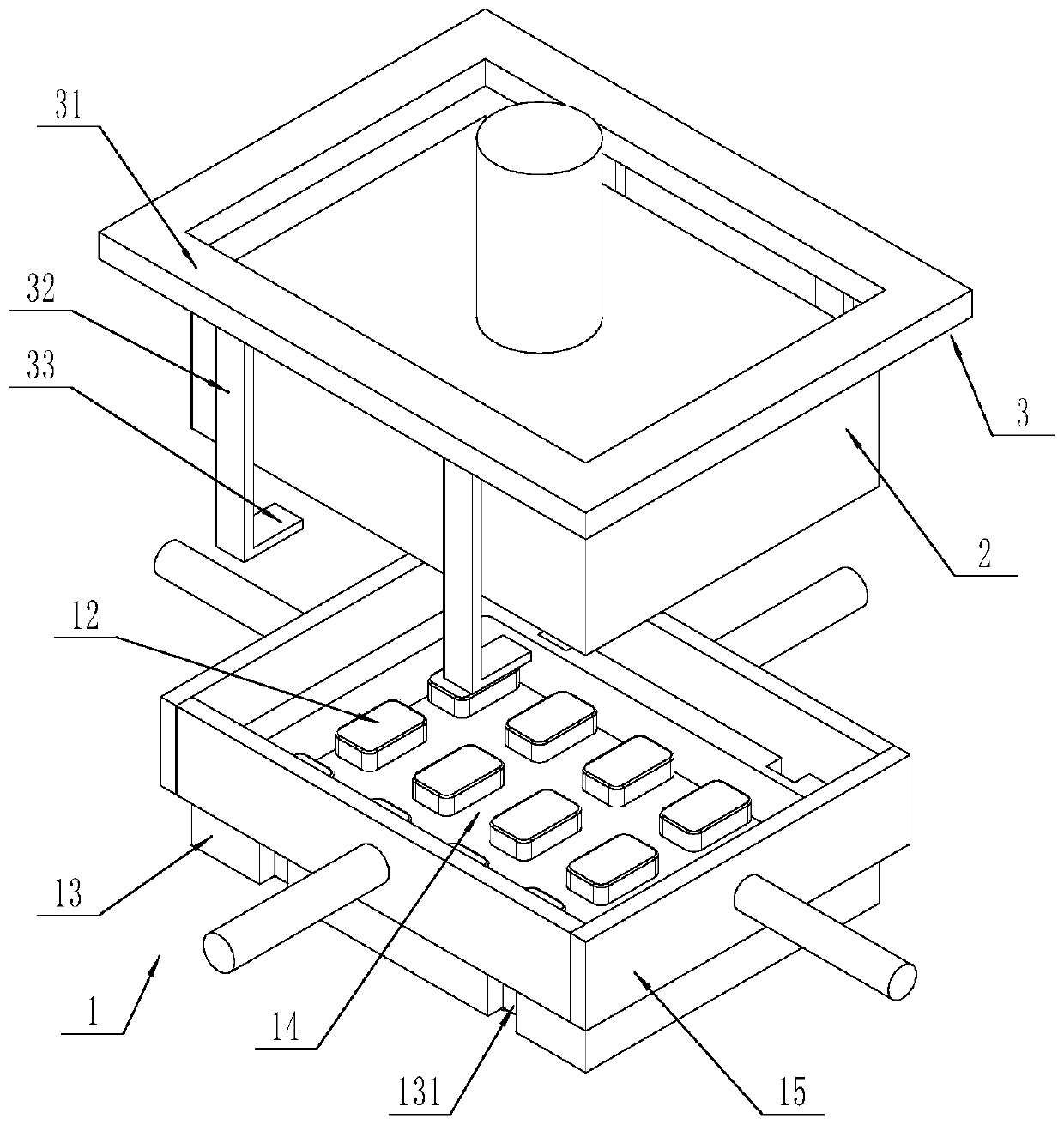
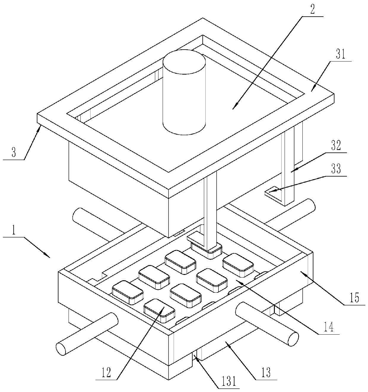
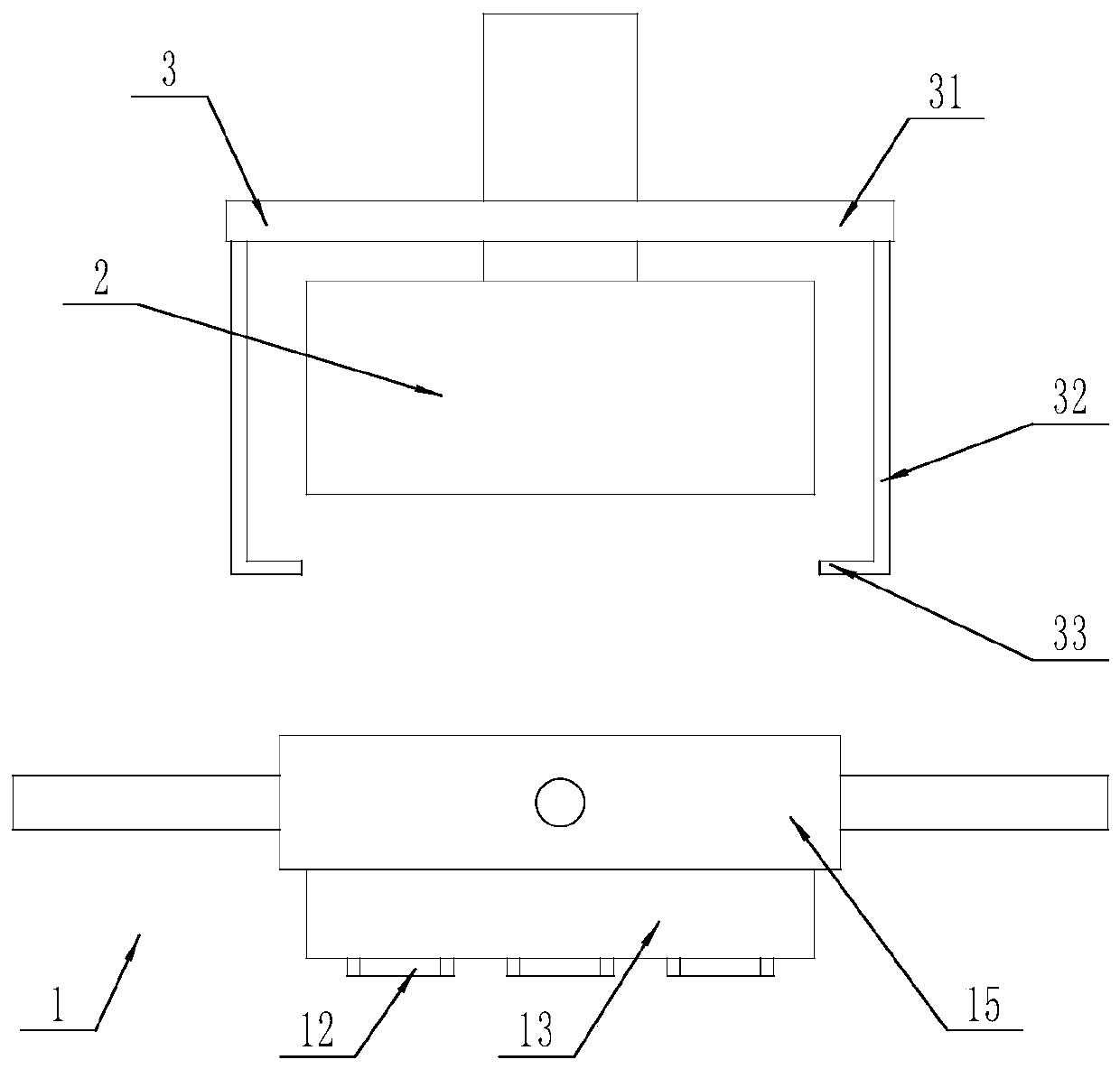
[0006] In order to solve the above-mentioned problems in the prior art, that is, in order to solve the problem that the existing die-casting machine is easy to cause damage to the cement board when the cement board is demoulded, the present disclosure provides a method for controlling the die-casting machine. The die-casting machine includes a bottom platform and a top platform capable of moving in the vertical direction, the aforementioned bottom platform includes a base with an accommodation cavity, a plurality of projections fixedly connected with the aforementioned base and located inside the aforementioned accommodation cavity in the horizontal direction, and located in the aforementioned accommodation cavity in the horizontal direction A frame in the cavity and capable of moving in the vertical direction, a bottom plate located on the inner side of the frame in the horizontal direction and capable of moving in the vertical direction, wherein the bottom plate is provided with a plurality of through holes, and each of the aforementioned through holes corresponds to one the aforementioned bumps;

Method used


Image

  • Die-casting machine and control method thereof
  • Die-casting machine and control method thereof
  • Die-casting machine and control method thereof

Examples


Embodiment Construction

[0066] It should be understood by those skilled in the art that the embodiments described below are only preferred embodiments of the present disclosure, and it does not mean that the present disclosure can only be realized through the preferred embodiments, and the preferred embodiments are only used to explain the present disclosure Technical principles are not intended to limit the protection scope of the present disclosure. Based on the preferred embodiments provided in the present disclosure, all other embodiments obtained by persons of ordinary skill in the art without making creative efforts should still fall within the protection scope of the present disclosure.

[0067] It should be noted that in the description of the present disclosure, the terms "center", "upper", "lower", "top", "bottom", "left", "right", "vertical", "horizontal", " Terms indicating directions or positional relationships such as "inner", "outer", etc. are based on the directions or positional rela...


PUM


Abstract

The invention provides a die-casting machine. The die-casting machine comprises a bottom platform and a top platform which can move in the vertical direction, wherein the bottom platform comprises a base with an accommodating cavity, a plurality of lug bosses which are fixedly connected to the base and are positioned inside the accommodating cavity in the horizontal direction, a side frame which is positioned in the accommodating cavity in the horizontal direction and can move in the vertical direction, and a bottom plate which is positioned at the inner side of a side frame in the horizontaldirection, and can move in the vertical direction; a plurality of through holes are formed in the bottom plate; and each through hole corresponds to a lug boss. A control method comprises the following steps: dropping a bottom plate to first preset height; enabling the bottom platform to receive concrete for a first time; dropping the side frame to first preset height; enabling the bottom platformto receive concrete for a second time; dropping the top platform and extruding the top of concrete; enabling the bottom plate and the side frame to simultaneously lift, and extruding the bottom of concrete, thereby forming a cement board by concrete. The die-casting machine disclosed by the invention can avoid a damage phenomenon during cement board de-moulding.

Description

technical field [0001] The disclosure belongs to the technical field of construction machinery, and specifically provides a die-casting machine and a control method thereof. Background technique [0002] The die-casting machine for cement board is a kind of equipment for die-casting concrete into cement board. Specifically, the die-casting machine generally includes a bottom platform and a top platform, wherein the bottom platform is usually provided with a mold (with grooves). The loose concrete is squeezed into a solid cement slab by placing rebar and wet concrete onto the bottom platform, then lowering the top platform and squeezing the concrete on the bottom platform. [0003] In order to reduce the amount of concrete on the premise of ensuring that the cement board has sufficient strength, the mold on the bottom platform is usually set in an uneven structure, so that one side of the cement board forms an uneven structure. [0004] However, the uneven mold often leads ...

Claims


Application Information

Patent Timeline
IPC IPC(8): B28B3/04B28B17/00
CPCB28B3/04B28B17/0081
Inventor 孟宪斌孟琪
Owner SHANDONG YUANBO BUILDING TECH CO LTD
Learn More