Neck brace
The technology of a neck brace and a support rod is applied to a neck brace. It can solve problems such as fatigue, soreness, and inability to move the neck, and achieve the effect of reliable support and improved applicability
- Summary
- Abstract
- Description
- Claims
- Application Information
AI Technical Summary
Problems solved by technology
Method used
Image
Examples
Embodiment 1
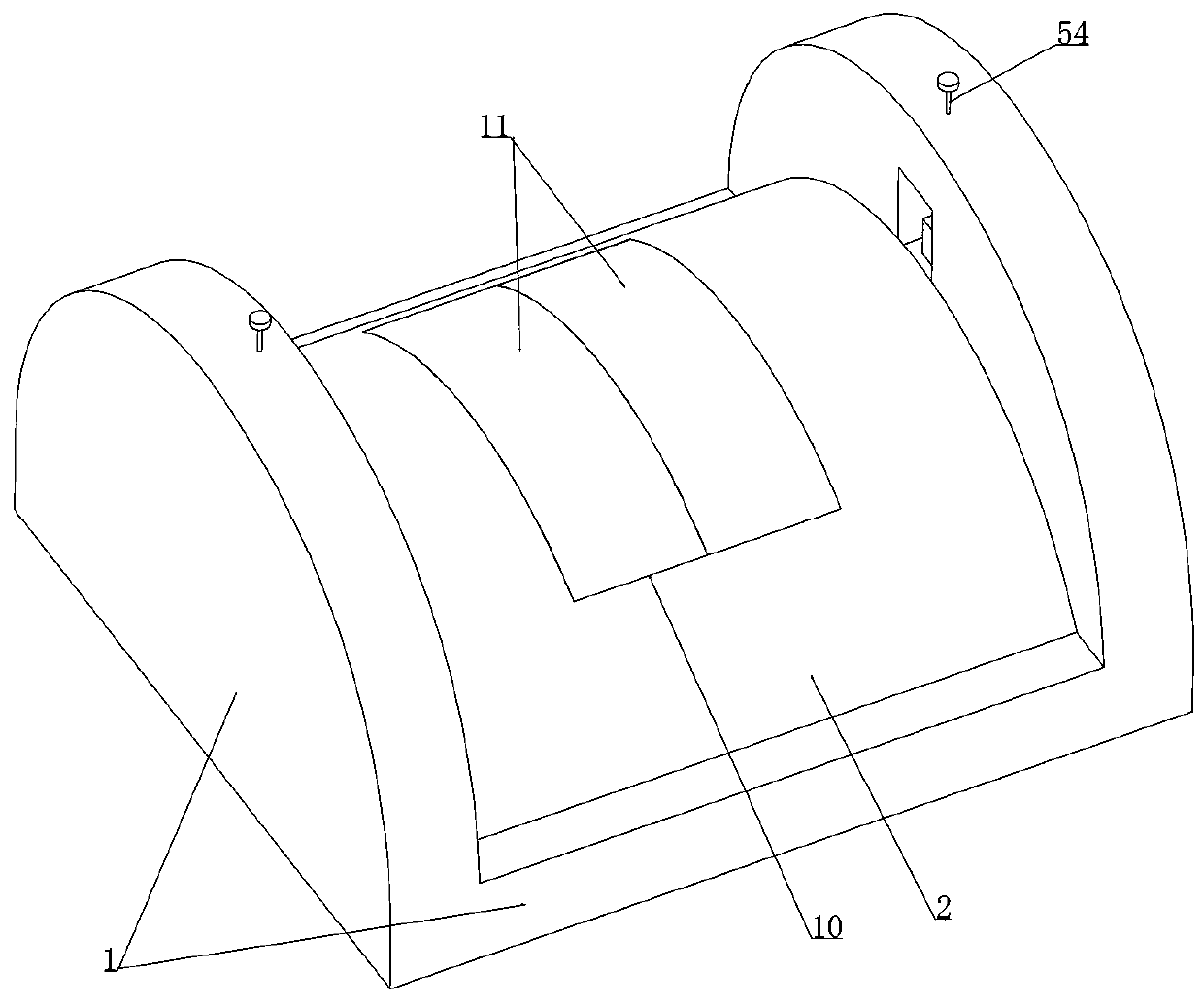
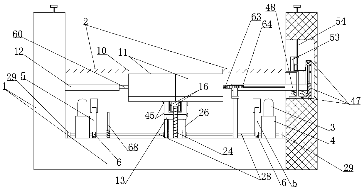
[0042] Embodiment 1, this embodiment provides a kind of neck collar, refer to the attached figure 1 As shown, the installation frame 1 is included, and the installation frame 1 is set in a U shape, and it is characterized in that, referring to the attached Figure 8 As shown, we slide and install an arc-shaped support plate 2 vertically on the upper end of the mounting frame 1, and the arc-shaped support plate 2 is connected with a lifting device (we can adjust the vertical position of the arc-shaped support plate 2 through the lifting device , and according to the different body shapes of different patients, the distance between the neck and the bed board is different when the patient lies flat with the pillow removed. We use the lifting device to adjust the height of the arc support plate 2 in the vertical position, so that the arc Shaped support plate 2 fits perfectly with the patient's neck to achieve reliable support for the patient's neck), refer to the attached Figure...
Embodiment 2
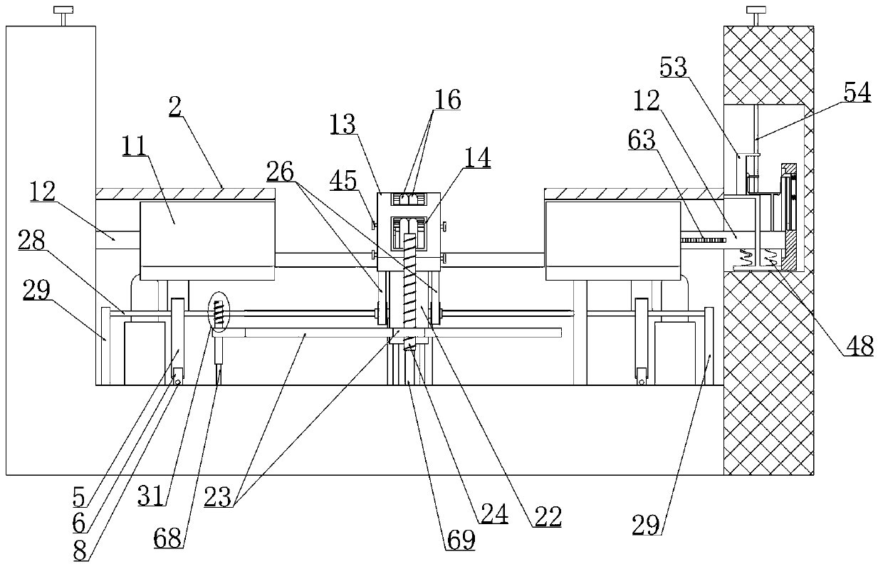
[0051] Embodiment 2, on the basis of embodiment 1, with reference to appended Figure 12 As shown, the arc-shaped lifting plate 13 is vertically slidably installed on the T-shaped frame 19 through the rectangular tube 22 integrally connected with it, and a cross 23 is vertically slidably installed on the arc-shaped support plate 2. Refer to the attached Figure 19 As shown, the rectangular cylinder 22 is horizontally slidably installed on the lateral extension part of the cross 23, referring to the attached Figure 10 As shown, the cross 23 is connected to the transmission device of the arc-shaped lifting plate 13, and the transmission device of the arc-shaped lifting plate 13 includes a lifting screw that is rotatably mounted on the longitudinal sides of the arc-shaped support plate 2 and is threadedly engaged with the longitudinal extension of the cross 23. 24. When we drive the two moving plates 11 to move opposite to each other through the driving device of the moving plat...
Embodiment 3
[0052] Embodiment 3, on the basis of embodiment 2, with reference to appended Figure 12 As shown, we are provided with four first cams 18 in this program and are respectively located on the longitudinal sides of the arc-shaped lifting plate 13, and the first cam shafts 25 located on the same longitudinal side of the arc-shaped lifting plate 13 pass through the first pulley group respectively. 26 is connected with the driving cylinder 27 that is installed in rotation on the rectangular cylinder 22 (as attached Figure 18 shown in), see attached Figure 10 As shown, the cam driving device includes a drive shaft 28 that is axially slidably mounted with the drive cylinder 27 and the two ends of the drive shaft 28 are respectively rotatably mounted on a support rod 29 that is vertically slidably mounted on the mounting bracket 1 (refer to the attached image 3 shown),
[0053] Refer to attached Figure 18 As shown, the drive cylinder 27 passes through the rectangular cylinder 2...
PUM
 Abstract
Description
Claims
Application Information
 - R&D
- Intellectual Property
- Life Sciences
- Materials
- Tech Scout
- Unparalleled Data Quality
- Higher Quality Content
- 60% Fewer Hallucinations
Browse by: Latest US Patents, China's latest patents, Technical Efficacy Thesaurus, Application Domain, Technology Topic, Popular Technical Reports.
© 2025 PatSnap. All rights reserved.Legal|Privacy policy|Modern Slavery Act Transparency Statement|Sitemap|About US| Contact US: help@patsnap.com


