
Ultrasonic motor and driving circuit thereof

An ultrasonic motor and drive circuit technology, which is applied in the direction of generators/motors, piezoelectric effect/electrostrictive or magnetostrictive motors, electrical components, etc., can solve the problems of large drive circuits and achieve volume reduction Effect

Active Publication Date: 2020-08-18
BEIJING MECHANICAL EQUIP INST
View PDF4 Cites 1 Cited by
  • Summary
  • Abstract
  • Description
  • Claims
  • Application Information

AI Technical Summary

Problems solved by technology

[0004] In order to solve the problem that the drive circuit of the ultrasonic motor is too large in the prior art, an embodiment of the present invention provides an ultrasonic motor and its drive circuit

Method used


Image

  • Ultrasonic motor and driving circuit thereof
  • Ultrasonic motor and driving circuit thereof
  • Ultrasonic motor and driving circuit thereof

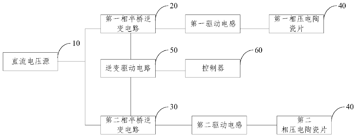
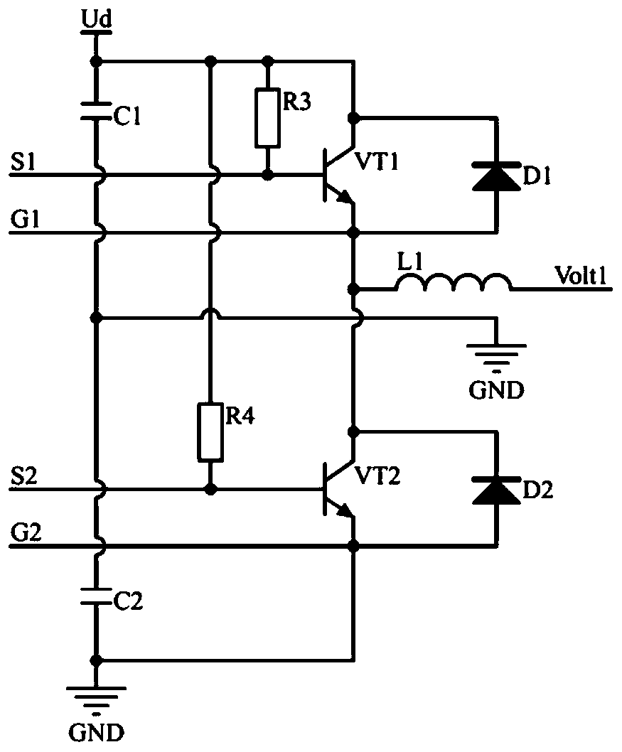
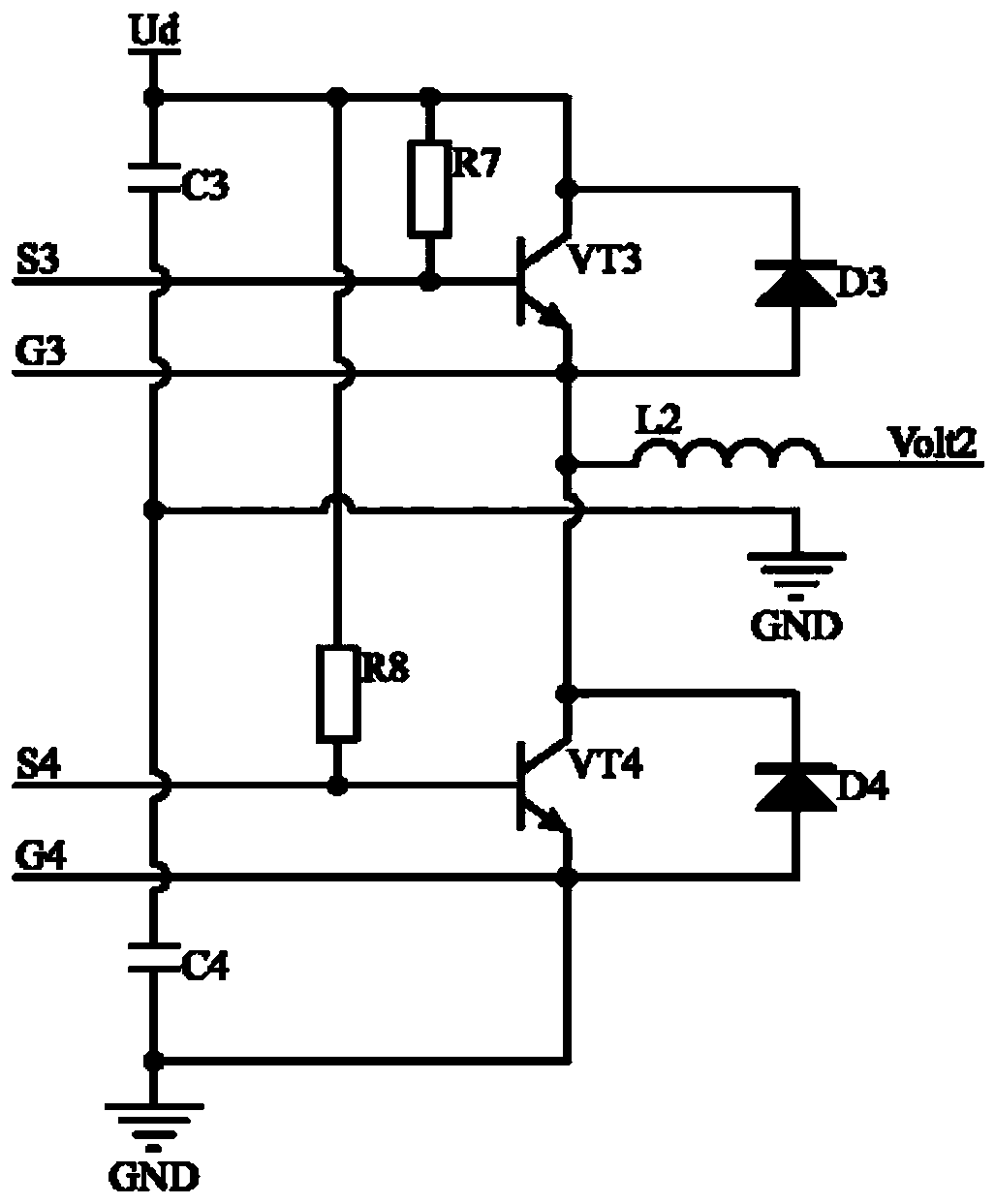
Examples


Embodiment Construction

[0023] In order to make the object, technical solution and advantages of the present invention clearer, the implementation manner of the present invention will be further described in detail below in conjunction with the accompanying drawings.

[0024] In order to solve the problem that the drive circuit of the motor is too large in the prior art, the application provides a drive circuit of the ultrasonic motor, which includes a voltage source and a drive inductance, wherein: one end of the drive inductance is electrically connected to the voltage source connected, the other end of the driving inductor is connected to the ultrasonic motor, and the ultrasonic motor belongs to a capacitive load and forms an LCR oscillation circuit resonant boost with the driving inductor. In this application, the principle of resonant boost is used to replace the transformer and the amplifier with the driving inductance, while realizing the driving of the ultrasonic motor, the volume of the drivi...


PUM


Abstract

The invention discloses an ultrasonic motor and a driving circuit thereof, and belongs to the technical field of driving circuits. The driving circuit comprises a voltage source and a driving inductor, one end of the driving inductor is electrically connected with the voltage source, the other end of the driving inductor is connected with the ultrasonic motor, and the ultrasonic motor belongs to acapacitive load and forms LCR oscillation circuit resonance boosting with the driving inductor. The driving inductor is used for replacing a transformer and an amplifier according to the resonance boosting principle, and the problem that in the prior art, the size of a driving circuit of an ultrasonic motor is too large is solved; and the effect of reducing the size of the driving circuit of theultrasonic motor is achieved.

Description

technical field [0001] The invention relates to the technical field of drive circuits, in particular to an ultrasonic motor and its drive circuit. Background technique [0002] Due to its simple and compact structure, easy miniaturization, fast response to braking, self-locking when power is off, good control characteristics, high positioning accuracy, non-magnetic and not affected by magnetic field, low speed, high torque, and low noise, it has been widely used in ultrasonic motors. It has broad application prospects and use value in high-tech fields such as aviation, aerospace, medical treatment, robotics, and precision instruments. [0003] At present, in some application fields, since the piezoelectric ceramics in the ultrasonic motor need to be driven by a large-amplitude high-frequency sinusoidal voltage, traditional drive circuits generally use transformers or amplifiers to provide high-frequency sinusoidal voltage for driving, but due to the transformer itself It is...

Claims


Application Information

Patent Timeline
Patent Type & Authority Applications(China)
IPC IPC(8): H02N2/14H02N2/16
CPCH02N2/14H02N2/16
Inventor 徐浩桐黄伯超王三舟许诺
Owner BEIJING MECHANICAL EQUIP INST
Learn More