Automatic filling device for clean pipe sealing ring

An automatic filling and tube sealing technology, applied in hand-held tools, manufacturing tools, etc., can solve the problems that only women with slender fingers are competent, the fingers of operators are worn out, and labor is occupied, so as to solve the problems of personal injury, location, etc. Accuracy and the effect of improving production efficiency

Active Publication Date: 2020-08-18
山东金润德新材料科技股份有限公司
View PDF5 Cites 0 Cited by
  • Summary
  • Abstract
  • Description
  • Claims
  • Application Information

AI Technical Summary

Problems solved by technology

However, the seemingly simple manual operation of filling the O-ring into the annular groove has taken up a lot of labor. When you have been engaged in the filling of the sealing ring for a long time, you have to repeatedly insert your fingers into the pipe every day. Occupational diseases that will cause the operator's fingers to be worn, scratched, injured or even deformed
Especially when filling the sealing ring into the 1 / 2" pipe joint, due to the small diameter of the pipe, generally only women with slender fingers can do it. Even such women can only work intermittently, that is, filling every day For the work of small diameter sealing rings, it is necessary to switch to other work for 3-5 days, and no one can bear the continuous work of filling small diameter sealing rings
[0004] Looking at the current situation of the clean pipe production industry, there is an urgent need for an automatic filling device for sealing rings to solve the problem of a large amount of labor force, reduce the labor intensity of workers, and reduce the injury to workers

Method used


Image

  • Automatic filling device for clean pipe sealing ring
  • Automatic filling device for clean pipe sealing ring
  • Automatic filling device for clean pipe sealing ring

Examples


Embodiment Construction

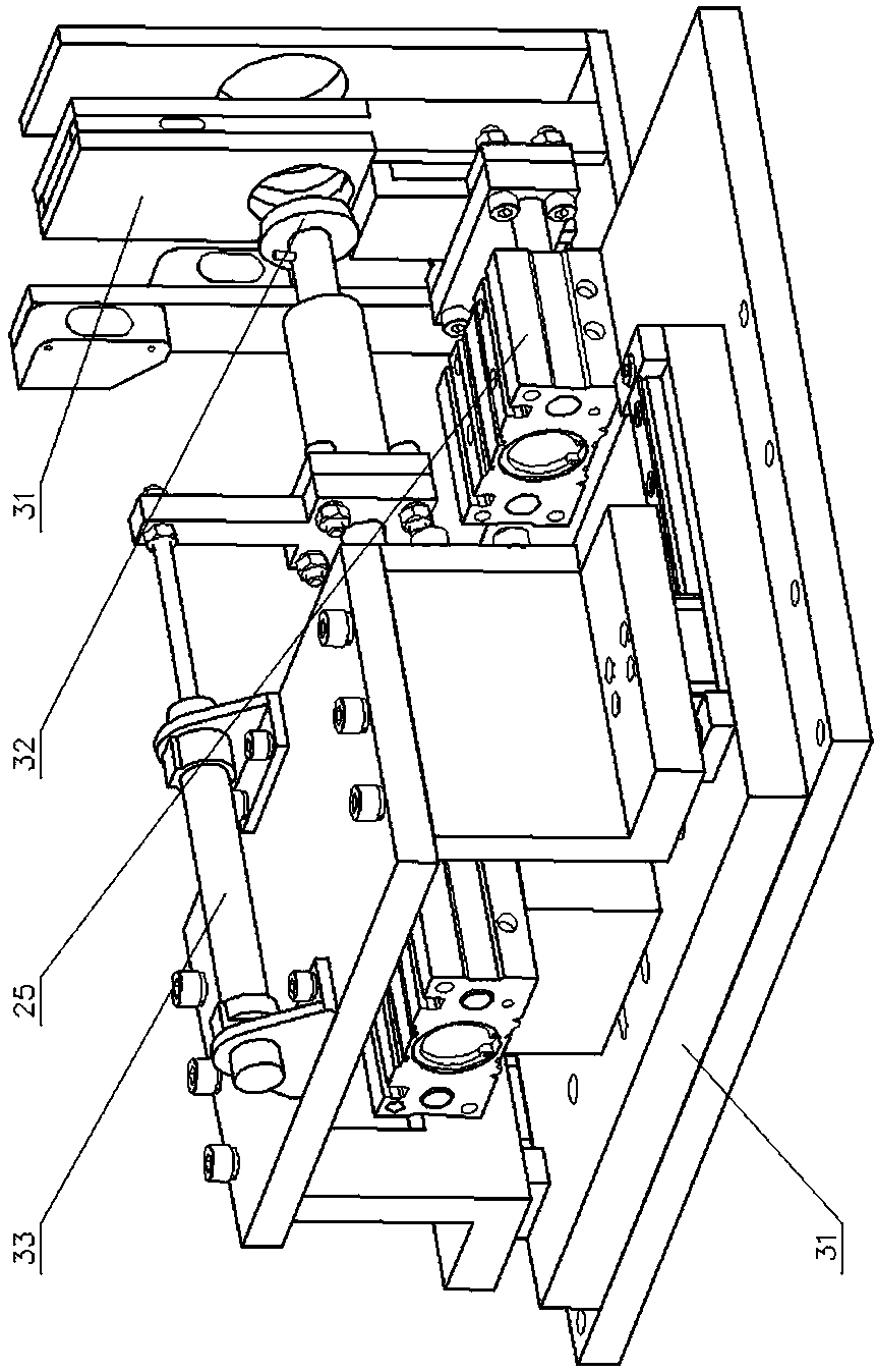
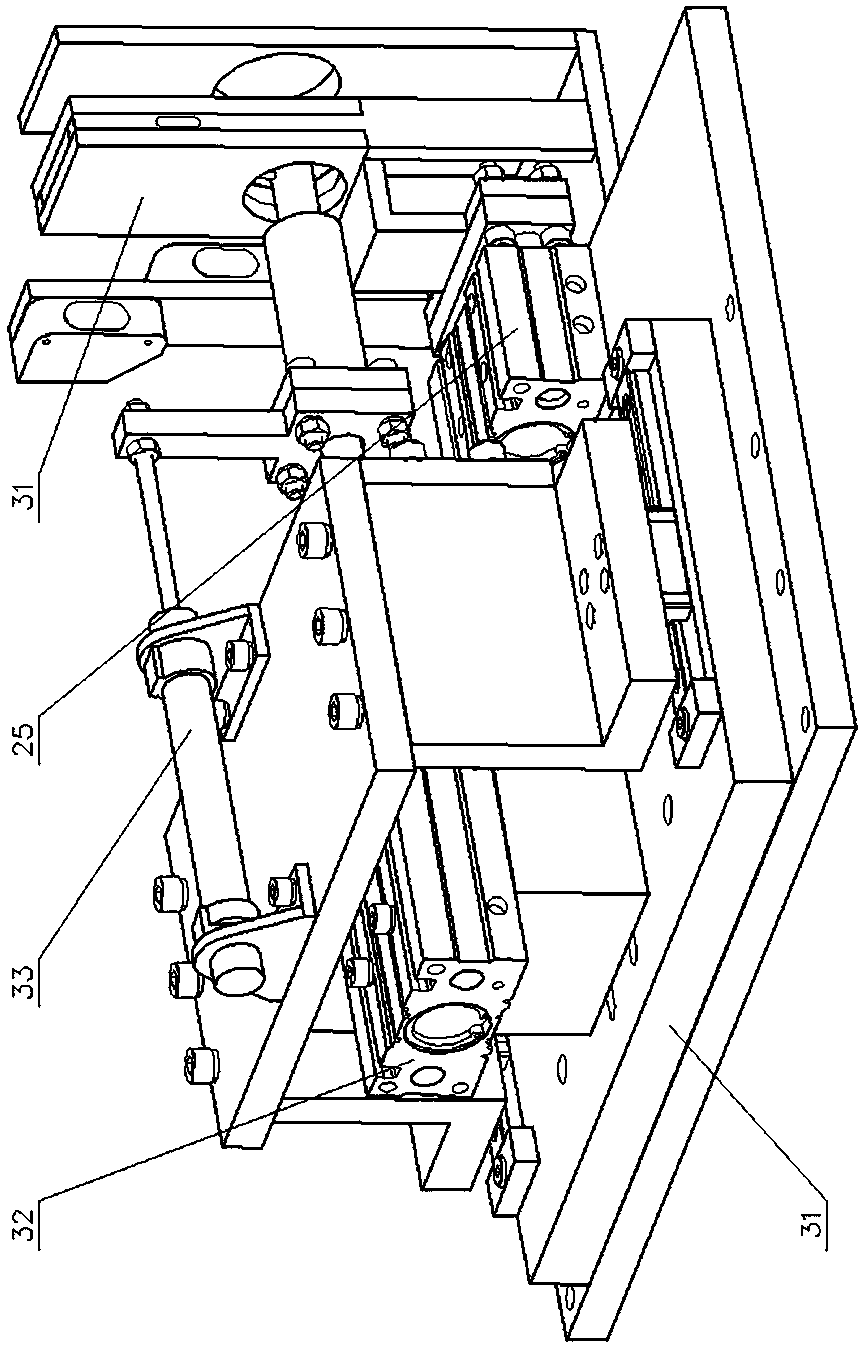
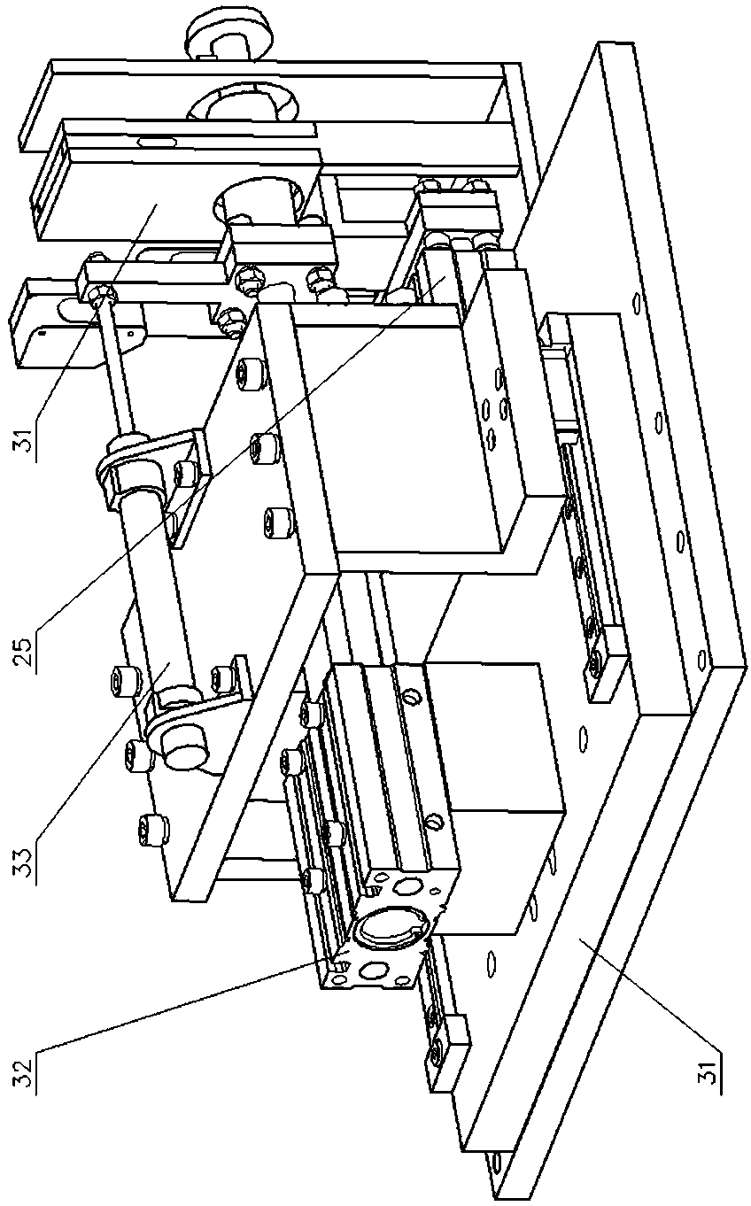
[0022] 3. Clean pipe sealing ring automatic filling device 31, loading frame 311, backing plate 312, linear guide rail 313, propulsion cylinder seat 314, backstop cylinder seat 315, transmission plate 316, socket seat plate 317, clean pipe socket 32, propulsion cylinder 321. Push cylinder block 322, push rod 323, guide head 324, hook 33, stop cylinder 331, stop cylinder block 332, stop rod 333, crank arm 334, stop sleeve 2, O-ring continuous supply Device 21, supply frame 211, dividing plate 212, vertical channel 214, photoelectric switch 25, bracket cylinder 251, bracket cylinder body 252, bracket rod 253, supporting plate.

[0023] exist Figure 1-Figure 8 In the shown embodiment: the partition plate 211 of the loading frame 31 of the clean pipe sealing ring automatic filling device 3 is in the shape of a rectangular flat plate and arranged horizontally, and the upper plane of the partition plate 211 is equipped with a pad in the shape of a rectangular flat plate near a shor...


PUM


Abstract

The invention provides an automatic filling device for a clean pipe sealing ring. The automatic filling device for the clean pipe sealing ring is characterized in that a base plate is mounted on the upper plane of a filling plate partition plate which is arranged horizontally; linear guide rails are mounted on the two sides of the upper plane of the base plate; a propulsion cylinder seat is mounted in the middle of the base plate; U-shaped two sides of a check cylinder seat are supported on the linear guide rails; a transmission plate is fixed to one end of the check cylinder seat; a verticalchannel is fixed to one end of the partition plate; a socket plate is arranged on the outer side of the vertical channel; and two photoelectric switches are mounted on a supporting leg which is supported on the partition plate. A propulsion cylinder body of a propulsion cylinder is mounted above the propulsion cylinder seat; a guide head is fixed to the end part of a propulsion rod after passing through a circular hole in the transmission plate; and a hanging hook is arranged at the position, close to the guide head, of the propulsion rod. The check cylinder body of a check cylinder is mountedabove the check cylinder seat; a crank arm is fixed to the end part of the check rod; a check sleeve is mounted on the propulsion rod in a sleeving manner; and one end of the check sleeve is fixedlyconnected with the crank arm. A supporting frame cylinder body of the supporting frame cylinder is mounted on the upper plane of the partition plate; and a supporting plate is fixed to the end part ofthe supporting frame. The automatic filling device for the clean pipe sealing ring can replace manual work and is high in automation degree.

Description

technical field [0001] The invention provides an automatic filling device for clean pipe seal rings, which belongs to a clean pipe joint seal ring filling machine with specific functions, and is mainly used for filling O-shaped seal rings into ring grooves of clean pipes. Background technique [0002] With the development of society and the improvement of people's living standards, the tap water pipes made of PVC materials can no longer meet people's pursuit of quality and healthy living needs, while a clean pipe made of stainless steel materials has quietly emerged and has been rapidly developed and developed. Promote apps. [0003] The drinking water pipe network in the building must be inseparable from various pipe joints, and the connection between the pipe joints and the pipes must be sealed. For this reason, an annular groove is generally arranged on the inner wall of each nozzle of the pipe joint, an O-shaped sealing ring is filled in the annular groove, and then thi...

Claims


Application Information

Patent Timeline
Patent Type & Authority Applications(China)
IPC IPC(8): B29C65/56B29C65/78B25B27/00
CPCB25B27/0028B29C65/56B29C65/7841B29C65/7858B29C66/61B29C66/63B29C66/74283
Inventor 贾衍光孙兆荣张剑武万程
Owner 山东金润德新材料科技股份有限公司
Why Eureka
Try Eureka