
Bent plate comprehensive test device

A comprehensive test and curved plate technology, which is applied in the field of aircraft strength test technology research, can solve the problem of inability to simulate the deformation process, the inability to realize the shear load at the end of the curved plate, the tensile, compressive and bending loads of the floor beam, the difficulty of control and the high risk And other issues

Active Publication Date: 2020-08-14
CHINA AIRPLANT STRENGTH RES INST
View PDF6 Cites 22 Cited by
  • Summary
  • Abstract
  • Description
  • Claims
  • Application Information

AI Technical Summary

Problems solved by technology

[0003] For this reason, all countries in the world are actively developing curved-plate comprehensive test devices. However, the current curved-plate comprehensive test devices have at least the following deficiencies: 1. Coordinated loading at one end of the test piece by multiple hydraulic actuators, while force control and There is a requirement for displacement control, and the control is difficult and risky; in addition, the real deformation process cannot be simulated locally on the test piece; 2. The load application has limitations, such as the end shear load, bending load, and floor load cannot be applied to the curved plate. Beam Tensile, Compressive and Bending Loads

Method used


Image

  • Bent plate comprehensive test device
  • Bent plate comprehensive test device
  • Bent plate comprehensive test device

Examples


Embodiment Construction

[0080] In order to make the purpose, technical solution and advantages of the application more clear, the technical solution in the embodiment of the application will be described in more detail below in conjunction with the drawings in the embodiment of the application. In the drawings, the same or similar reference numerals denote the same or similar elements or elements having the same or similar functions throughout. The described embodiments are some, but not all, embodiments of the application. The embodiments described below by referring to the figures are exemplary, and are intended to explain the present application, and should not be construed as limiting the present application. Based on the embodiments in this application, all other embodiments obtained by persons of ordinary skill in the art without creative efforts fall within the protection scope of this application. Embodiments of the present application will be described in detail below in conjunction with th...


PUM


Abstract

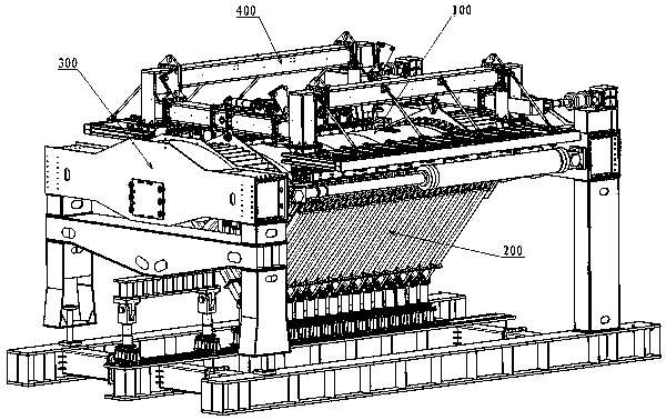
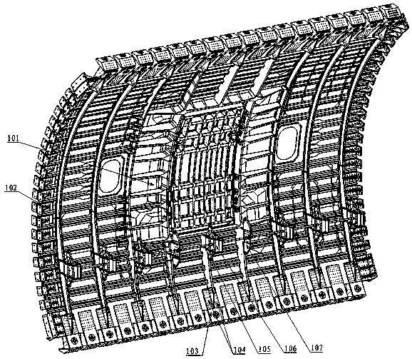
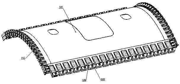
The invention belongs to the field of airplane strength test technology research, and particularly relates to a bent plate comprehensive test device which comprises a test piece assembly, a triangularassembly array, an axial and bending loading assembly and a shearing loading assembly. The triangular assembly array comprises triangular assemblies, and floor beam loading triangular assemblies which are used for applying an annular load, a floor beam stretching load, a floor beam compressing load and a floor beam bending load to a test piece; the axial and bending loading assembly comprises a base platform, a fixed end assembly and a movable end assembly and is used for applying an end load to the shearing loading assembly; the shearing loading assembly comprises a bearing frame, a straightedge loading frame and a pull rod assembly and is used for applying shearing force in opposite directions to the two straight edges of the test piece. According to the bent plate comprehensive test device, loads such as stretching / compressing, shearing, air tightness, bending, end shearing and stretching / compressing and bending of the floor beam can be independently applied, combined loading of any load can be conducted, and meanwhile application of all the loads does not interfere with each other.

Description

technical field [0001] The application belongs to the field of aircraft strength test technology research, in particular to a curved plate comprehensive test device. Background technique [0002] The comprehensive strength test of the curved plate mainly studies the static, fatigue and damage tolerance performance of the curved plate of the fuselage, and provides the basis for the design analysis, structural optimization and damage repair of the fuselage panel and other structures. It plays a very important role in pre-study and type verification. [0003] For this reason, all countries in the world are actively developing curved-plate comprehensive test devices. However, the current curved-plate comprehensive test devices have at least the following deficiencies: 1. Coordinated loading at one end of the test piece by multiple hydraulic actuators, while force control and There is a requirement for displacement control, and the control is difficult and risky; in addition, th...

Claims


Application Information

Patent Timeline
IPC IPC(8): G01N3/00G01N3/08G01N3/20G01N3/24G01N3/02G01M3/00B64F5/60
CPCB64F5/60G01M3/00G01N3/00G01N3/02G01N3/08G01N3/20G01N3/24G01N2203/0017G01N2203/0019G01N2203/0023G01N2203/0025G01N2203/0026G01N2203/0676
Inventor 柴亚南李崇高敏陈丽敏彭新未王彬文陈向明林亮亮
Owner CHINA AIRPLANT STRENGTH RES INST
Learn More