A diaphragm pressure tank with joint sealing structure

A sealing structure and air pressure tank technology, which is applied in the sealing of engines, the configuration of water supply tanks, construction, etc., can solve problems such as bolt unscrewing and affecting the air pressure tank sealing

Active Publication Date: 2021-03-26
上海南汇压力容器厂有限公司
View PDF7 Cites 0 Cited by
  • Summary
  • Abstract
  • Description
  • Claims
  • Application Information

AI Technical Summary

Problems solved by technology

[0004] Bolts are used to connect the tank body, inner tank, and ring plate. However, during the actual operation of the air pressure tank, the air pressure tank will be continuously vibrated by the water flow, so it is easy to cause the bolts to unscrew and affect the airtightness of the air pressure tank.

Method used


Image

  • A diaphragm pressure tank with joint sealing structure
  • A diaphragm pressure tank with joint sealing structure
  • A diaphragm pressure tank with joint sealing structure

Examples


Embodiment Construction

[0031] The present invention will be described in further detail below in conjunction with the accompanying drawings.

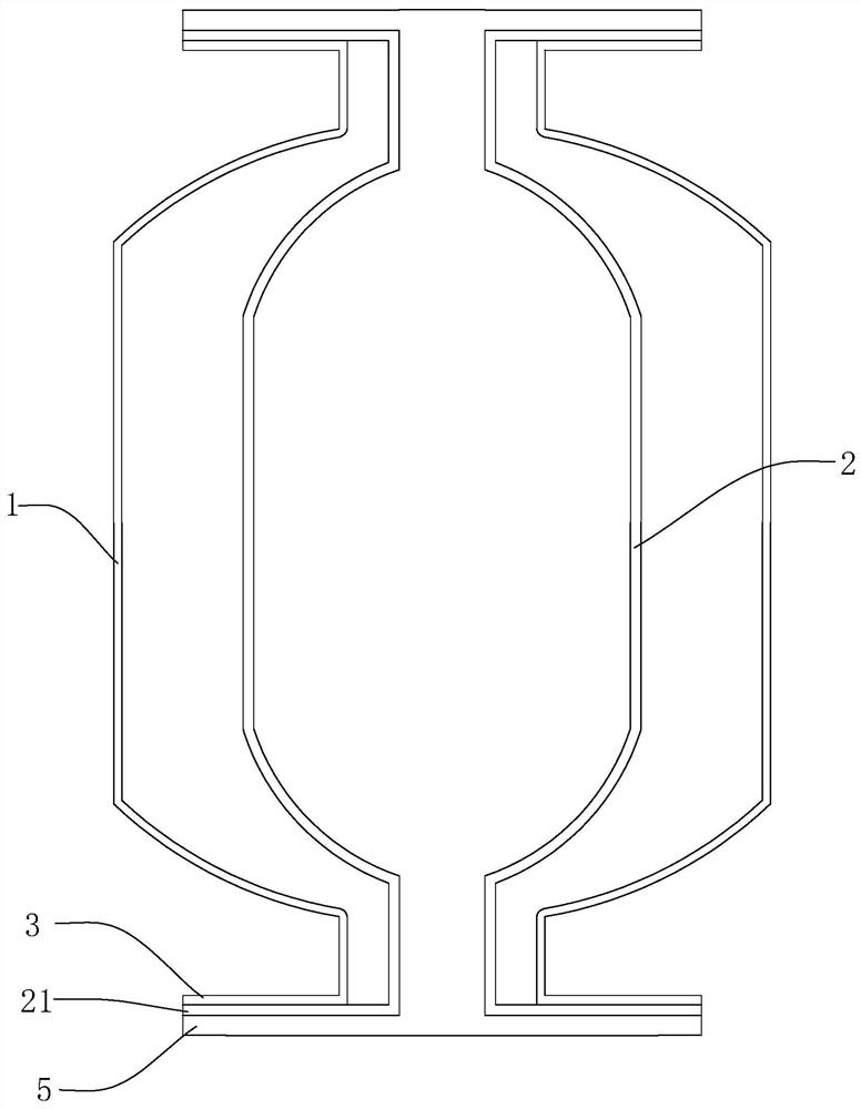
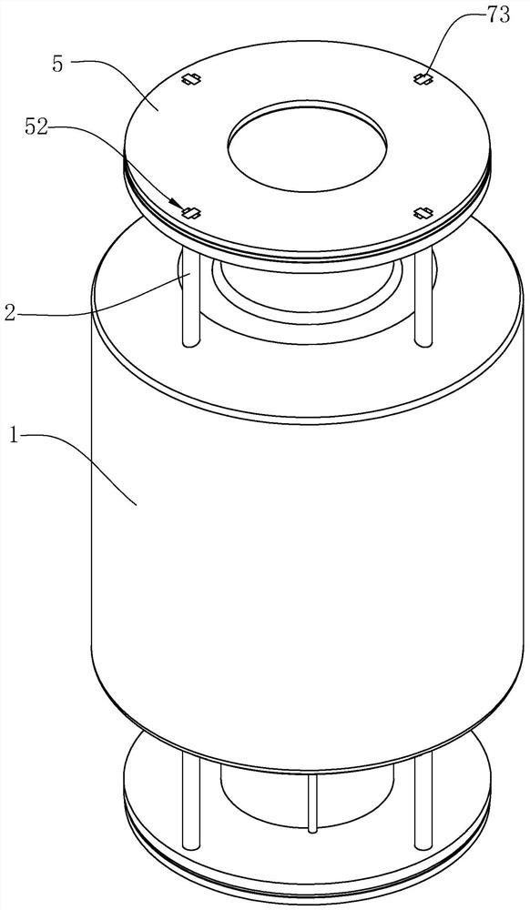
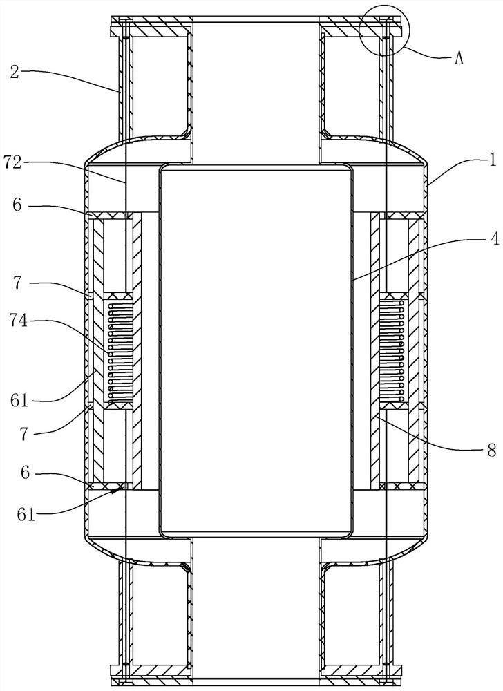
[0032] Such as figure 2 with image 3 As shown, a diaphragm pressure tank with a joint sealing structure includes a tank body 1 and an inner tank 4, the tank body 1 is placed vertically, flanges 3 are arranged at both ends of the tank body 1 in the vertical direction, and the inner tank body 4 Both ends in the vertical direction protrude from the tank body 1 to form an annular extension 41, the extension 41 is in contact with the flange 3, and ring plates 5 are arranged on both sides of the tank body 1 in the vertical direction. 5 and the flange 3 squeeze the extension 41 to realize the sealed connection between the tank body 1 and the liner 4 .

[0033] Such as figure 2 with image 3 As shown, a pair of fixed rings 6 are coaxially welded on the inner wall of the tank body 1, the fixed rings 6 are arranged along the horizontal direction, and a slip ring...


PUM


Abstract

The invention relates to a diaphragm air pressure tank with a joint seal structure. The diaphragm air pressure tank comprises a tank body, an inner container and annular plates, wherein flange platesare arranged at two ends of the tank body, a pair of parallel fixed rings are arranged on the inner wall of the tank body, pressure guide holes are formed in the fixed rings along the axes of the fixed rings seal rings are fixed on the inner circumferences of the fixed rings, and a pair of sliding rings moving oppositely or reversely are coaxially arranged between the fixed rings, the out circumferences and inner circumferences of the sliding rings are in sliding fit with the inner wall of the tank body and the seal rings respectively, and return springs are arranged between the sliding rings;through holes are formed in the circumference of an extension part at intervals; communication pipes are arranged in the circumference between the tank body and the flange plates at intervals; and pull wires penetrating through the communication pipes, the through holes and the pressure guide holes are arranged between the sliding rings and the annular plates. The tank has the effects that increase or decrease of air pressure in the tank body is controlled, extrusion and loosening between the annular plates and flange are achieved, and stable sealed connection of the inner container to the tank body is further achieved.

Description

technical field [0001] The invention relates to the technical field of pressure tanks, in particular to a diaphragm pressure tank with a joint sealing structure. Background technique [0002] Such as figure 1 , the existing air pressure tank is mainly composed of a tank body 1 and an inner tank 2, high-pressure gas is stored between the tank body 1 and the inner tank 2, the inner tank 2 is used for water storage, and flanges 3 are arranged at both ends of the tank body 1 , the two ends of the liner 2 protrude from the tank body 1 and fit with the flange 3, and then use the ring plate 5 to squeeze the two ends of the liner 2 to abut on the flange 3, and the flange 3 and the ring plate 5 are fixedly connected by bolts; during the water supply process, when the water pressure in the system decreases, the high-pressure gas squeezes the water in the liner 2 to replenish the system, thereby reducing the change of the system water pressure and raising the water pressure in the sys...

Claims


Application Information

Patent Timeline
Patent Type & Authority Patents(China)
IPC IPC(8): E03B11/06E03B11/08F16J15/04F16J15/06
CPCE03B11/06E03B11/08F16J15/04F16J15/06
Inventor 徐军
Owner 上海南汇压力容器厂有限公司
Why Eureka
Try Eureka