


Quick Research
Generate reliable direction feasibility study reports for your R&D in just a few steps.

Technical Q&A
Discover and master advanced knowledge NOW. Basics, ideas, possibilities, all at once.

Find Solutions
As an expert in R&D theories, this can generate solutions to your technical problems instantly.

Evaluate Feasibility
Analyze your overall solution with one click, know your potential R&D risks in advance.

Monitor Landscape
Get weekly tech updates, stay abreast of the latest tech innovations and key insights.
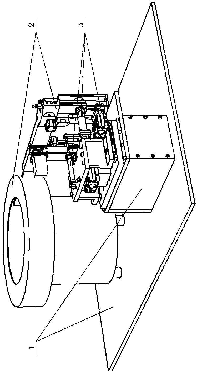
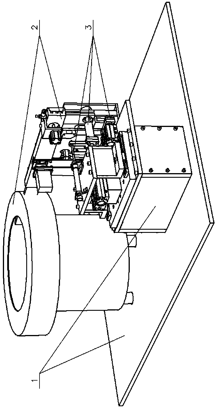
Loading machine of clean pipe connector seal ring
A sealing ring and pipe joint technology, which is used in the field of clean pipe and pipe joint sealing ring filling machines, can solve the problems of scratches, deformation, and only women with slender fingers are competent.
- Summary
- Abstract
- Description
- Claims
- Application Information
AI Technical Summary
Problems solved by technology
Method used
Image


Examples
Embodiment Construction
[0031] 1. Rack 11, mounting plate 12, support box 2, O-ring continuous supply device 21, supply rack 211, partition 212, vertical channel 213, camera leg 214, photoelectric switch 22, feeding device 221, upper Material tray 222, transverse channel 223, compressed air connector 224, window 23, sorting device 231, sorting cylinder 232, sorting board 233, camera 24, clamping cylinder 241, clamping cylinder block 242, clamping rod 243, Pressure plate 25, bracket cylinder 251, bracket cylinder block 252, bracket rod 253, bracket 3, automatic filling device for clean pipe sealing ring 31, filling frame 311, backing plate 312, linear guide 313, advancing cylinder block 314, stopper Cylinder block 315, transmission plate 316, socket base plate 317, clean pipe socket 32, push cylinder 321, push cylinder block 322, push rod 323, guide head 324, hook 33, backstop cylinder 331, backstop cylinder block 332, The backstop rod 333, the arm 334, and the backstop sleeve.
[0032] exist Figur...
PUM
 Abstract
Description
Claims
Application Information
 - R&D Engineer
- R&D Manager
- IP Professional
- Industry Leading Data Capabilities
- Powerful AI technology
- Patent DNA Extraction
Browse by: Latest US Patents, China's latest patents, Technical Efficacy Thesaurus, Application Domain, Technology Topic, Popular Technical Reports.
© 2024 PatSnap. All rights reserved.Legal|Privacy policy|Modern Slavery Act Transparency Statement|Sitemap|About US| Contact US: help@patsnap.com