
An automatic clamping bending die

A bending mold and automatic clamping technology, which is applied in the direction of manufacturing tools, storage devices, metal processing equipment, etc., can solve the problem that the bending effect cannot be guaranteed, the bending efficiency of the bending mold is low, and the bending position of the bending plate is biased. Problems such as inclination can be solved to achieve the effect of reducing gravity, reducing weight and ensuring the bending effect

Active Publication Date: 2021-10-15
台州市森博五金有限公司
View PDF0 Cites 0 Cited by
  • Summary
  • Abstract
  • Description
  • Claims
  • Application Information

AI Technical Summary

Problems solved by technology

[0004] The purpose of the present invention is to provide a subject to solve the above-mentioned background technology that the bending efficiency of the bending mold is low and the plate needs to be bent manually, which is very unsafe, especially when the plate is large, manual bending will also The problem that the bending position of the folded plate is skewed and the bending effect cannot be guaranteed

Method used


Image

  • An automatic clamping bending die
  • An automatic clamping bending die
  • An automatic clamping bending die

Examples


Embodiment Construction

[0038] The following will clearly and completely describe the technical solutions in the embodiments of the present invention with reference to the accompanying drawings in the embodiments of the present invention. Obviously, the described embodiments are only some, not all, embodiments of the present invention. Based on the embodiments of the present invention, all other embodiments obtained by persons of ordinary skill in the art without creative efforts fall within the protection scope of the present invention.

[0039] see Figure 1-8 , the present invention provides a technical solution:

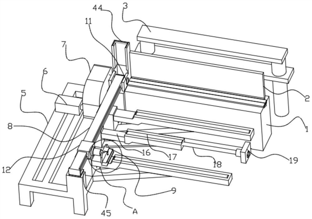
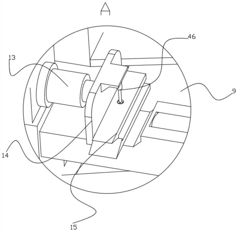
[0040] An automatic clamping and bending mold, including a lower mold backing plate 1, an upper mold pressing block 2, a positioning device 3, an automatic clamping device 4, and the automatic clamping device 4 includes a support frame 5, a servo motor 6, a reduction box 7, a rotating Rod 8, clamping mechanism 9, main supporting mechanism 10;

[0041] The support frame 5 is fixedly co...


PUM


Abstract

The invention discloses an automatic clamping bending mold in the technical field of bending molds, which includes a backing plate for a lower bending mold, a pressure block for an upper mold, a positioning device, and an automatic clamping device. The automatic clamping device includes a support frame, a servo motor, Gear box, rotating rod, clamping mechanism, main support mechanism, the support frame is fixedly connected to the ground, a servo motor is arranged behind the top left side of the support frame, the output shaft of the servo motor is connected to the reducer box, and a rotating shaft is arranged behind the top surface of the support frame, and the rotating shaft The axis is at the same level as the center line of the top surface of the backing plate of the lower die. This invention mainly solves the problem of the rapid development of China's manufacturing industry in recent years, which is a huge market for bending dies, but the bending efficiency of current bending dies is low. And it is very unsafe to manually hold the plate for bending, especially when the plate is large, manual bending will also cause the bending position of the bent plate to deviate, which cannot guarantee the bending effect well.

Description

technical field [0001] The invention relates to the field of bending molds, in particular to an automatic clamping bending mold. Background technique [0002] The bending mold is a tool used by the bending machine to process and form the plate. This mold is composed of different parts. Different molds are composed of different parts. It is used to make the plate into a specific shape and shape under the pressure of the bending machine. In recent years, China's manufacturing industry has developed rapidly, which is a huge market for bending molds. However, the current bending molds have low bending efficiency and need to manually hold the plate for bending, which is very inconvenient. Safety, especially when the plate is large, manual bending will also cause the bending position of the folded plate to deviate, which cannot guarantee the bending effect well. [0003] Based on this, the present invention designs the subject matter to solve the above-mentioned problems. Conte...

Claims


Application Information

Patent Timeline
Patent Type & Authority Patents(China)
IPC IPC(8): B21D5/04B21D43/00
CPCB21D5/042B21D43/003
Inventor 罗层
Owner 台州市森博五金有限公司
Learn More